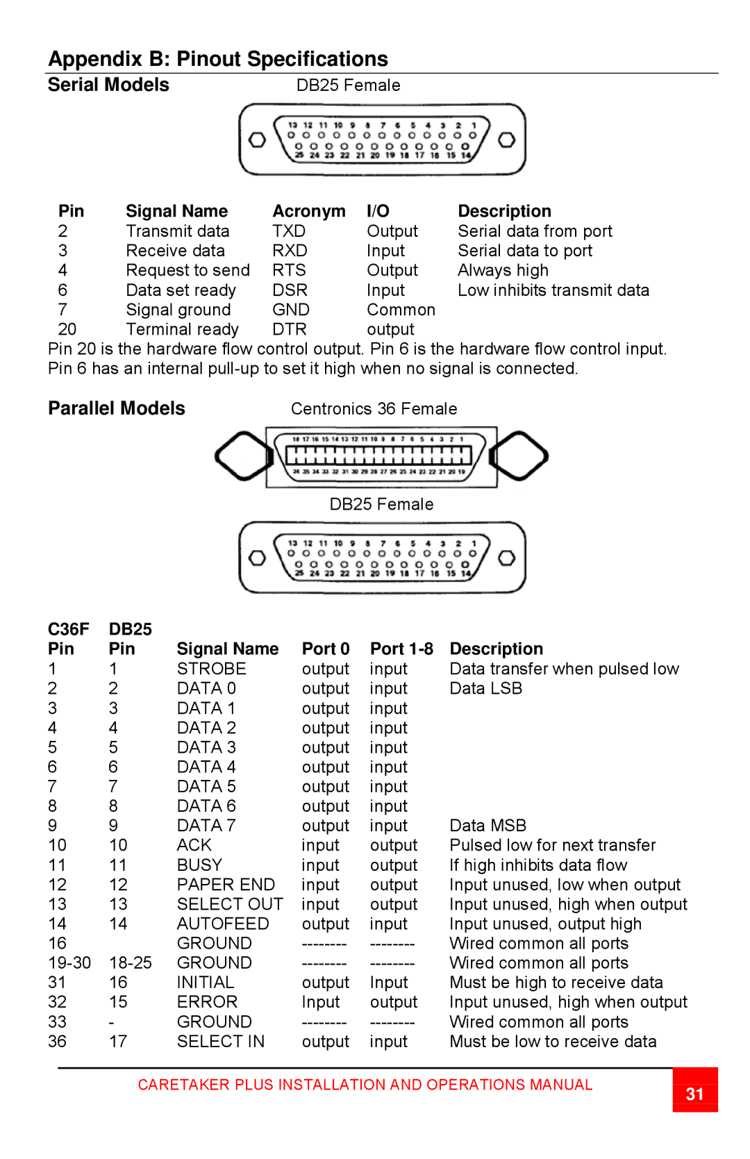
CTP-8S specifications
The Rose Electronic CTP-8S is an advanced KVM (keyboard, video, mouse) switch designed to meet the demands of modern IT environments. This device allows users to control multiple computers from a single console, enhancing both efficiency and productivity. With its robust features and cutting-edge technologies, the CTP-8S stands out in the market of KVM solutions.One of the key features of the CTP-8S is its ability to support multiple users. This KVM switch can handle up to eight different computer systems, providing seamless switching between them. This capability is particularly beneficial in environments like data centers, studios, and security operations, where rapid access to multiple devices is essential.
The CTP-8S employs advanced video technology, supporting resolutions up to 1920x1200 at 60Hz. This ensures that users can enjoy clear and sharp visuals, an essential aspect for tasks that require precise monitoring and analysis. The switch supports a variety of video interfaces, making it versatile for different setups, including HDMI, DVI, and VGA connections.
Another standout characteristic of the CTP-8S is its USB compatibility. The device allows users to connect standard USB keyboards and mice, ensuring compatibility with a wide range of peripherals. Furthermore, the CTP-8S supports USB 2.0 hubs, enabling users to connect additional devices such as flash drives and printers, enhancing productivity in multi-tasking environments.
The CTP-8S also features a user-friendly interface, with a straightforward switching mechanism that allows for quick and effortless transitions between computers. Users can switch between systems using hotkeys or the provided remote control, making the device exceptionally convenient to operate in dynamic settings.
In terms of reliability, the CTP-8S boasts a durable design built to withstand the rigors of continuous use. Its robust metal housing provides protection against physical damage, while advanced thermal management ensures optimal performance even during extended operation.
Overall, the Rose Electronic CTP-8S is an exceptional KVM switch that combines user-friendly features with advanced technologies to support complex IT needs. Its ability to manage multiple systems simultaneously, high-quality video output, and compatibility with various peripherals make it an ideal choice for businesses and professionals looking to optimize their workflow.

