Manuals
/
Rotel
/
Home Audio
/
Stereo System
Rotel
RX-1052 Making Connections, AC Input, Master Power Switch, 12V TRIGGER Connections u
Models:
RX-1052
1
14
26
26
Download
26 pages
4.25 Kb
11
12
13
14
15
16
17
18
Troubleshooting
Signal to Noise Ratio 45 dB
Custom Setup Procedures
Tone Adjustments qGQ
TUNING Buttons 4M
Setting the Tuner Region
RR-AT96Remote Control
Placement
VOLUME Knob w VOLUME Buttons C
Safety
Page 14
Image 14
Page 13
Page 15
Page 14
Image 14
Page 13
Page 15
Contents
RX-1052
AM/FM Stereo Receiver
10 cm
RX-1052 AM/FM Stereo Receiver
10 cm 4 in
4 in
English
2 RR-AT96Remote Control
1 Front Panel Controls
RX-1052 AM/FM Stereo Receiver
Important Safety Instructions
FCC Information
POWER CONSUMPTION 300 WATTS
3 Rear Panel Connections
4 Antenna Connections
English
RX-1052 AM/FM Stereo Receiver
5 Speaker and TV
POWER CONSUMPTION 300 WATTS
AM/FM STEREO RECEIVER
POWER CONSUMPTION 300 WATTS
6 CD and Phono
7 Tape
POWER CONSUMPTION 300 WATTS
POWER CONSUMPTION 300 WATTS
8 DVD and SAT/CABLE/HDTV
9 VCR
RX-1052 AM/FM Stereo Receiver
English
10 Zone Connections and Preamp Output Connection
POWER CONSUMPTION 300 WATTS
AM/FM STEREO RECEIVER
Zone 2-4Outputs sdf
Contents
RX-1052 AM/FM Stereo Receiver
ZONE Connections uisdf
English
Multi Zone Operation
About Rotel
Key Features
Placement
Getting Started
Phono Inputs h Phono Ground y
Rear Panel
Cable selection
CD Inputs j
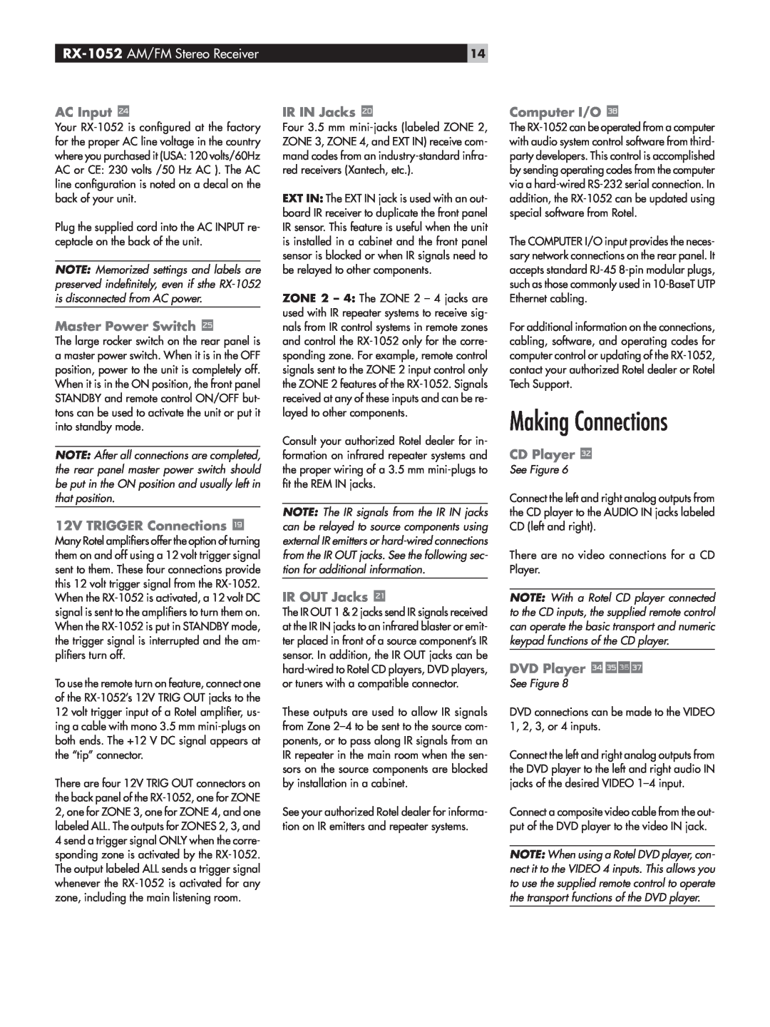
AC Input
Master Power Switch \
Making Connections
12V TRIGGER Connections u
VCR l
Cable, Satellite, or HDTV Tuner
Audio Recorder k
Phono Turntable yh
RR-AT96Remote Control
USING THE RX-1052
Controls, Buttons and Features
uisdf
Headphones Jack
STANDBY Button POWER Switch \
VOLUME Knob w VOLUME Buttons C
Remote Sensor
Power and Standby On/Off
TUNING Buttons 4M
TUNE/PRESET Button T/P Button N
Volume Adjustments wC
Muting the Sound L
Tone Adjustments qGQ
Selecting Inputs
Selecting Speakers 9J
Using Station Presets =EF
AM/FM Tuning
Tuning Stations 4M
Frequency Direct Tuning EP
RDS Reception 6DTUV
Custom Setup Procedures
Turning the Display On/Off D
Controlling other Rotel Components EBQK
Setting a Remote Zone Maximum Volume
Setting the Tuner Region
Setting Power Mode
Setting a Remote Zone Turn-onVolume
Multi Zone Operation
Remote Zone Power On/Off
Controlling Remote Zones from the Main Room
7werBCQRS
MORE INFORMATION Protection Circuit
Troubleshooting
Controlling a Zone from the Remote Location ABCQ
RX-1052 AM/FM Stereo Receiver
Video
Specifications
Audio
FM Tuner
Rotel of America
10-10 Shinsen-Cho Shibuya-Ku Tokyo Japan
Phone +81 Fax +81
54 Concord Street North Reading, MA USA Phone +1
Top
Page
Image
Contents