
M2100 specifications
The RuggedCom M2100 is a robust and versatile managed switch designed specifically for the demanding environment of industrial applications. With its rugged construction, the M2100 is built to withstand extreme temperatures, vibrations, and other harsh conditions typically found in sectors such as utilities, transportation, and manufacturing.One of the standout features of the RuggedCom M2100 is its ability to support a wide temperature range, from -40°C to +85°C, ensuring reliable operation in various climates. Its compact design allows for easy integration into existing systems while still providing high performance and flexibility.
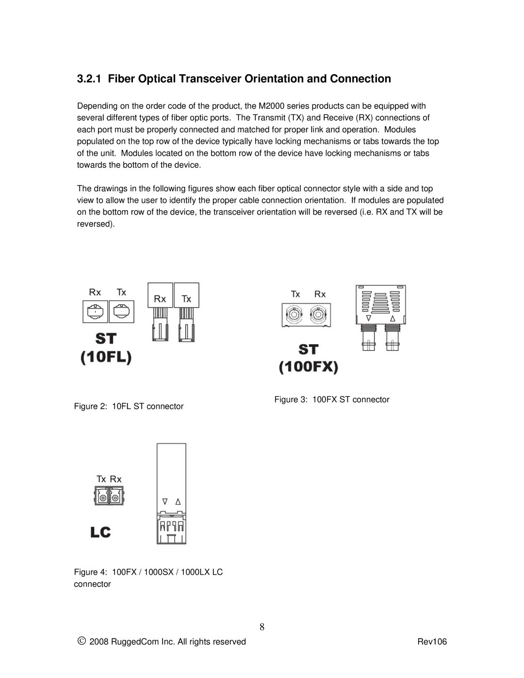
The M2100 offers various Ethernet ports, including 10/100BASE-TX and optical fiber options, to accommodate different connectivity needs. It supports Layer 2 and Layer 3 switching capabilities, providing organizations with the flexibility to manage their networks efficiently. The device also supports Quality of Service (QoS) to prioritize critical data traffic, which is crucial in applications where timely data transmission is vital.
Security is a key focus with the RuggedCom M2100. The switch features robust security protocols, including access controls, VLANs, and port security, which help to prevent unauthorized access and ensure a more secure network environment. This is particularly important in industrial settings where data integrity and security are paramount.
The M2100 is equipped with advanced diagnostic capabilities, enabling users to monitor network performance and troubleshoot issues proactively. Its support for SNMP (Simple Network Management Protocol) allows for remote management and monitoring, giving operators greater control over their network environments.
The switch is also designed for ease of use, featuring a user-friendly web interface for configuration and management. Additionally, it supports various network management protocols, ensuring that it can integrate seamlessly into existing systems without significant modifications.
In conclusion, the RuggedCom M2100 managed switch stands out as a reliable and feature-rich solution for industrial networking. With its rugged design, extensive security features, and advanced diagnostic capabilities, it is well-suited for organizations that require a durable and high-performing networking solution capable of operating under challenging conditions. Whether for utility networks, transportation systems, or manufacturing processes, the RuggedCom M2100 delivers the performance and reliability that industrial sectors demand.