Device Connections
Using the ISO Connector
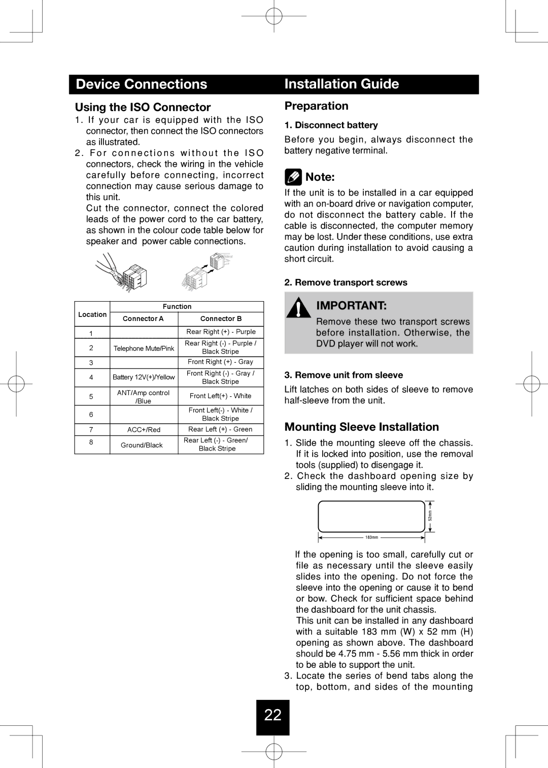
1. If your car is equipped with the ISO connector, then connect the ISO connectors as illustrated.
2 . F o r c o n n e c t i o n s w i t h o u t t h e I S O connectors, check the wiring in the vehicle carefully before connecting, incorrect connection may cause serious damage to this unit.
Cut the connector, connect the colored leads of the power cord to the car battery, as shown in the colour code table below for speaker and power cable connections.
Location | Function | ||
Connector A | Connector B | ||
| |||
|
|
| |
1 |
| Rear Right (+) - Purple | |
2 | Telephone Mute/Pink | Rear Right | |
Black Stripe | |||
|
| ||
3 |
| Front Right (+) - Gray | |
4 | Battery 12V(+)/Yellow | Front Right | |
Black Stripe | |||
|
| ||
5 | ANT/Amp control | Front Left(+) - White | |
/Blue | |||
|
| ||
6 |
| Front | |
| Black Stripe | ||
|
| ||
7 | ACC+/Red | Rear Left (+) - Green | |
8 | Ground/Black | Rear Left | |
| Black Stripe | ||
|
| ||
Installation Guide
Preparation
1. Disconnect battery
Before you begin, always disconnect the battery negative terminal.
![]() Note:
Note:
If the unit is to be installed in a car equipped with an
2. Remove transport screws
IMPORTANT:
Remove these two transport screws before installation. Otherwise, the DVD player will not work.
3. Remove unit from sleeve
Lift latches on both sides of sleeve to remove
Mounting Sleeve Installation
1.Slide the mounting sleeve off the chassis. If it is locked into position, use the removal tools (supplied) to disengage it.
2.Check the dashboard opening size by sliding the mounting sleeve into it.
If the opening is too small, carefully cut or file as necessary until the sleeve easily slides into the opening. Do not force the sleeve into the opening or cause it to bend or bow. Check for sufficient space behind the dashboard for the unit chassis.
This unit can be installed in any dashboard with a suitable 183 mm (W) x 52 mm (H) opening as shown above. The dashboard should be 4.75 mm - 5.56 mm thick in order to be able to support the unit.
3.Locate the series of bend tabs along the top, bottom, and sides of the mounting
22