Operation
Use the controls in the Picture Menu to calibrate each DHD Controller input to achieve optimum picture quality.
The DHD Controller has been designed to incorporate setup and calibration standards established by the Imaging Science Foundation (ISF). The ISF has developed carefully crafted,
All signal types require separate processing. Therefore, you need to calibrate each DHD Controller input separately.
1. When you change a picture quality setting, save the change to a
Note preset afterwards. Otherwise, the change will be lost when a different input is selected. (Picture quality settings are saved for each input separately.) For information about saving settings, refer to Memory Presets on page 58.
2.For best results, Runco recommends that you set ConstantContrast to Off before adjusting Brightness, Contrast and other image quality settings in this menu (refer to ConstantContrast on page 61). After you have completed the initial calibration, set ConstantContrast to On if desired.
Although it may be possible to obtain satisfactory picture quality using the naked eye and regular program material, Runco recommends using the following calibration tools for best results:
•External test pattern source – Ovation Multimedia, Digital Video Essentials or AVIA test DVD or equivalent.
•A blue filter (provided with many test DVDs), for color level and tint adjustments.
Connect your test pattern source to the input that you are calibrating and proceed as follows. Perform the adjustments in the order listed here.
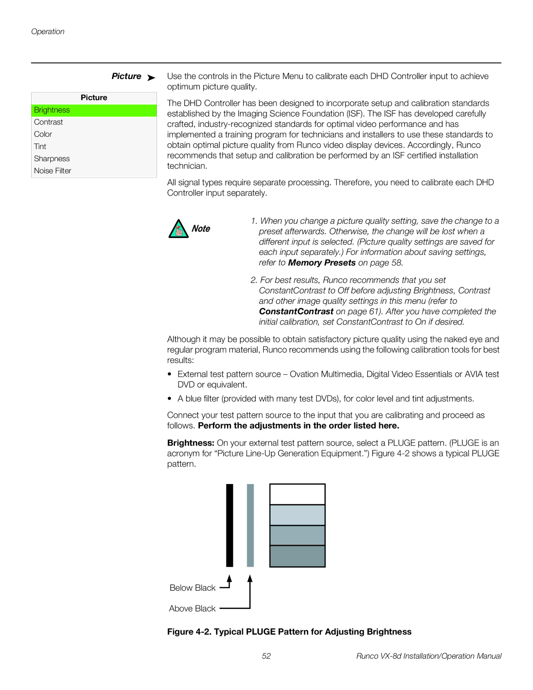
Brightness: On your external test pattern source, select a PLUGE pattern. (PLUGE is an acronym for “Picture
Below Black ![]()
Above Black
Figure 4-2. Typical PLUGE Pattern for Adjusting Brightness
52 | Runco |
