Align the holes in the lower handle with those of the
upper handle and insert the hex bolts through both holes.
On the left side, install the lock washer and hex nut
and tighten finger tight.
On the right side, insert the hex nut into the hex hole in the cord insulator and thread onto the hex
bolt on the dght side. Make certain that the curved portion of the cord insulator is resting flush against the upper handle.
Tighten the hardware firmly using an adjustable wrench or suitable tightening tool.
Refer to Figure 2 for proper alignment of hardware and handles.
Attachingthe Blade/ MotorControlto the Upper
Handle
Holding the blade / motor control, which is attached to the mower, route the power cord as it is shown in Figure 2 along the right side of the handle.
Mount the blade / motor control to the upper handle by inserting its two pedestals into the two holes in the upper handle. Refer to Figure 2 for correct
positioning on the upper handle.
Close the rear cover on the blade / motor control
and using the small washer head screws included in the hardware kit, screw them into the holes in the rear cover with a phillips screwdriver, thus securing the blade / motor control to the upper handle.
Route the power cord through the cord insulator on
the right handle as shown in Figure 3.
Upper Handle
Hex Nut
Lower Handle
Power Cord
Figure 3
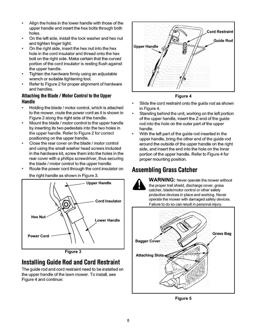
InstallingGuideRodandCordRestraint
The guide rod and cord restraint need to be installed on the upper handle of the lawn mower. To install, see Figure 4 and continue:
Cord Restraint
Guide Rod
Upper Handle
Figure 4
Slide the cord restraint onto the guide rod as shown in Figure 4.
Standing behind the unit, working on the left portion of the upper handle, insert the
With the left part of the guide rod inserted in the upper handle, bring the other end of the guide rod around the outside of the upper handle on the right side, and insert the end into the hole on the inner portion of the upper handle. Refer to Figure 4 for proper mounting position.
AssemblingGrassCatcher
WARNING: Never operate the mower without the proper trail shield, discharge cover, grass catcher, blade/motor control or other safety protective devices in place and working, Never operate the mower with damaged safety devices, Failure to do so can result in personal injury,
Grass Bag
Bagger Cover
Attaching Slots_
Figure 5
