ASSEMBLY INSTRUCTIONS
3.Press the Flail Head Bottom on by matching the pin guides with the Pivot Pins (Fig. 7).
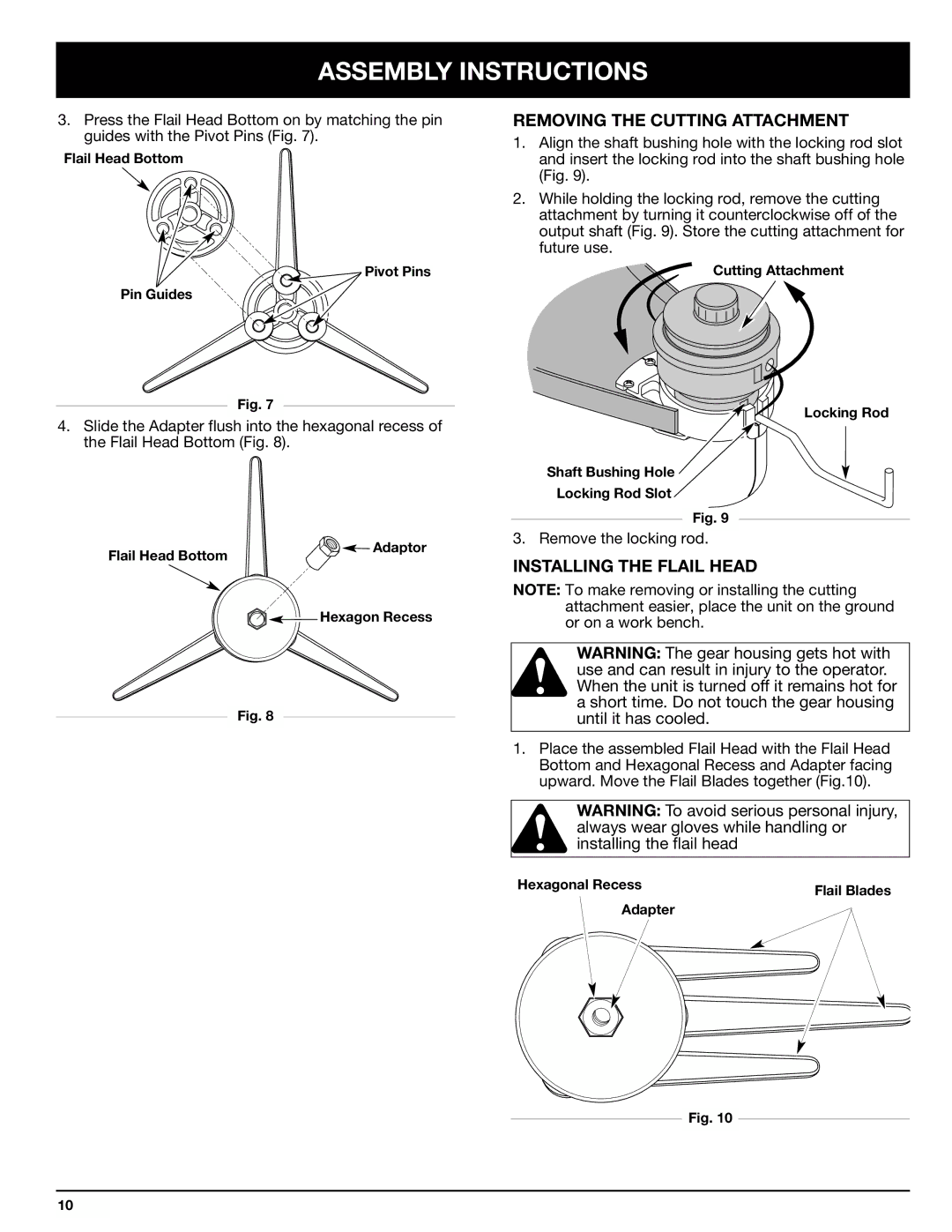
REMOVING THE CUTTING ATTACHMENT
1. Align the shaft bushing hole with the locking rod slot |
Flail Head Bottom
Pin Guides
![]() Pivot Pins
Pivot Pins
and insert the locking rod into the shaft bushing hole |
(Fig. 9). |
2. While holding the locking rod, remove the cutting |
attachment by turning it counterclockwise off of the |
output shaft (Fig. 9). Store the cutting attachment for |
future use. |
Cutting Attachment
Fig. 7
4.Slide the Adapter flush into the hexagonal recess of the Flail Head Bottom (Fig. 8).
Locking Rod
Shaft Bushing Hole
Locking Rod Slot
Fig. 9
Flail Head Bottom
Adaptor
3. Remove the locking rod.
INSTALLING THE FLAIL HEAD
![]()
![]()
![]() Hexagon Recess
Hexagon Recess
Fig. 8
NOTE: To make removing or installing the cutting attachment easier, place the unit on the ground or on a work bench.
WARNING: The gear housing gets hot with use and can result in injury to the operator. When the unit is turned off it remains hot for a short time. Do not touch the gear housing until it has cooled.
1.Place the assembled Flail Head with the Flail Head Bottom and Hexagonal Recess and Adapter facing upward. Move the Flail Blades together (Fig.10).
WARNING: To avoid serious personal injury, always wear gloves while handling or installing the flail head
Hexagonal Recess | Flail Blades |
| |
Adapter |
|
Fig. 10
10