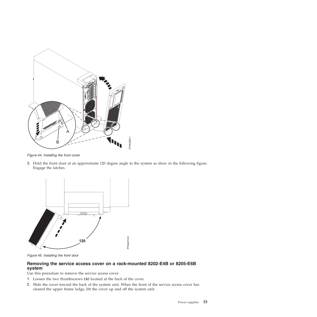
Figure 44. Installing the front cover
3.Hold the front door at an approximate 120 degree angle to the system as show in the following figure. Engage the latches.
Figure 45. Installing the front door
Removing the service access cover on a
Use this procedure to remove the service access cover.
1.Loosen the two thumbscrews (A) located at the back of the cover.
2.Slide the cover toward the back of the system unit. When the front of the service access cover has cleared the upper frame ledge, lift the cover up and off the system unit.