ASSEMBLY INSTRUCTIONS
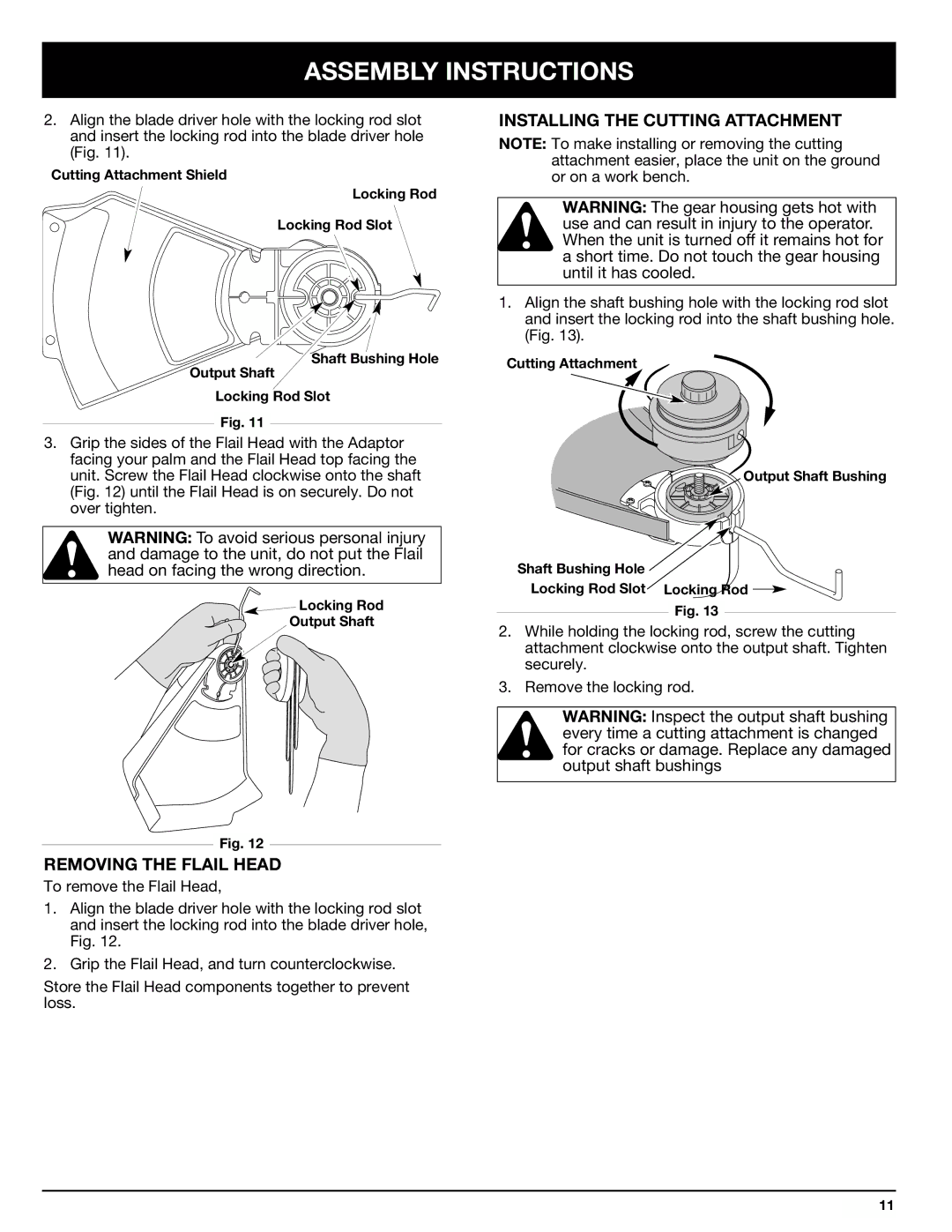
2.Align the blade driver hole with the locking rod slot and insert the locking rod into the blade driver hole (Fig. 11).
Cutting Attachment Shield
Locking Rod
Locking Rod Slot
Shaft Bushing Hole
Output Shaft
Locking Rod Slot
Fig. 11
3.Grip the sides of the Flail Head with the Adaptor facing your palm and the Flail Head top facing the unit. Screw the Flail Head clockwise onto the shaft (Fig. 12) until the Flail Head is on securely. Do not over tighten.
WARNING: To avoid serious personal injury and damage to the unit, do not put the Flail head on facing the wrong direction.
![]() Locking Rod
Locking Rod
Output Shaft
Fig. 12
REMOVING THE FLAIL HEAD
To remove the Flail Head,
1.Align the blade driver hole with the locking rod slot and insert the locking rod into the blade driver hole, Fig. 12.
2.Grip the Flail Head, and turn counterclockwise.
Store the Flail Head components together to prevent loss.
INSTALLING THE CUTTING ATTACHMENT
NOTE: To make installing or removing the cutting attachment easier, place the unit on the ground or on a work bench.
WARNING: The gear housing gets hot with use and can result in injury to the operator. When the unit is turned off it remains hot for a short time. Do not touch the gear housing until it has cooled.
1.Align the shaft bushing hole with the locking rod slot and insert the locking rod into the shaft bushing hole. (Fig. 13).
Cutting Attachment
Output Shaft Bushing
Shaft Bushing Hole
Locking Rod Slot Locking Rod ![]()
Fig. 13
2.While holding the locking rod, screw the cutting attachment clockwise onto the output shaft. Tighten securely.
3.Remove the locking rod.
WARNING: Inspect the output shaft bushing every time a cutting attachment is changed for cracks or damage. Replace any damaged output shaft bushings
11