MAINTENANCE
![]() WARNING:
WARNING:
When servicing, use only identical Ryobi replacement parts. Use of any other part may create a hazard or cause product damage.
CLEANING BASE ASSEMBLY
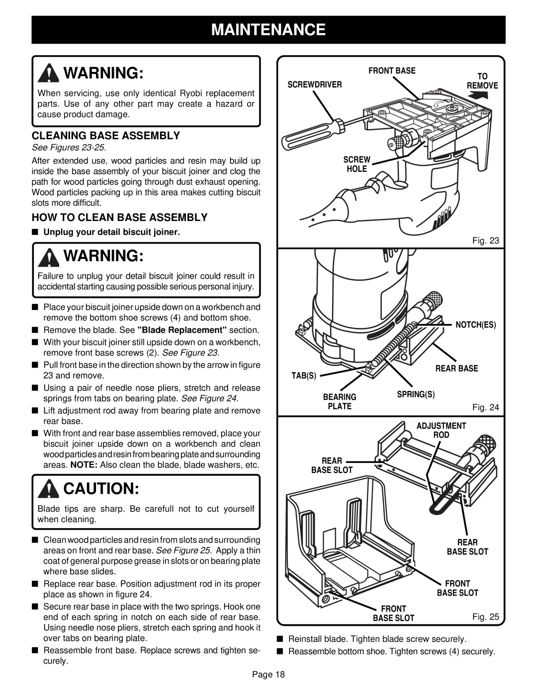
See Figures 23-25.
After extended use, wood particles and resin may build up inside the base assembly of your biscuit joiner and clog the path for wood particles going through dust exhaust opening. Wood particles packing up in this area makes cutting biscuit slots more difficult.
HOW TO CLEAN BASE ASSEMBLY
■Unplug your detail biscuit joiner.
| FRONT BASE |
SCREWDRIVER | TO |
REMOVE |
2
3
SCREW
HOLE
Fig. 23
![]() WARNING:
WARNING:
Failure to unplug your detail biscuit joiner could result in accidental starting causing possible serious personal injury.
■Place your biscuit joiner upside down on a workbench and remove the bottom shoe screws (4) and bottom shoe.
■Remove the blade. See "Blade Replacement" section.
■With your biscuit joiner still upside down on a workbench, remove front base screws (2). See Figure 23.
■Pull front base in the direction shown by the arrow in figure 23 and remove.
■Using a pair of needle nose pliers, stretch and release springs from tabs on bearing plate. See Figure 24.
■Lift adjustment rod away from bearing plate and remove rear base.
■With front and rear base assemblies removed, place your biscuit joiner upside down on a workbench and clean wood particles and resin from bearing plate and surrounding areas. NOTE: Also clean the blade, blade washers, etc.
![]() CAUTION:
CAUTION:
Blade tips are sharp. Be carefull not to cut yourself when cleaning.
■Clean wood particles and resin from slots and surrounding areas on front and rear base. See Figure 25. Apply a thin coat of general purpose grease in slots or on bearing plate where base slides.
■Replace rear base. Position adjustment rod in its proper place as shown in figure 24.
■Secure rear base in place with the two springs. Hook one end of each spring in notch on each side of rear base. Using needle nose pliers, stretch each spring and hook it over tabs on bearing plate.
■Reassemble front base. Replace screws and tighten se- curely.
| NOTCH(ES) |
TAB(S) | REAR BASE |
| |
BEARING | SPRING(S) |
PLATE | Fig. 24 |
| ADJUSTMENT |
| ROD |
REAR |
|
BASE SLOT |
|
| REAR |
| BASE SLOT |
| FRONT |
| BASE SLOT |
FRONT | Fig. 25 |
BASE SLOT |
■Reinstall blade. Tighten blade screw securely.
■Reassemble bottom shoe. Tighten screws (4) securely.
Page 18