OPERATION
EDGE PLANING
See Figures 10 and 11.
Your planer comes with an adjustable edge guide for precision edge planing. It can be attached to either side of your planer and is useful when planing long and un- even surface boards.
ATTACHING THE EDGE GUIDE
Assemble the edge guide and edge guide bracket using the carriage head screw, washer and retaining knob. Attach the edge guide assembly to the desired side of the planer, ensuring the locating tab on the edge guide bracket fits into the locating tab hole. Install thumb screw and tighten securely.
To adjust the edge guide to the width of cut, loosen the retaining knob and adjust to the desired position. Re- tighten the retaining knob securely.
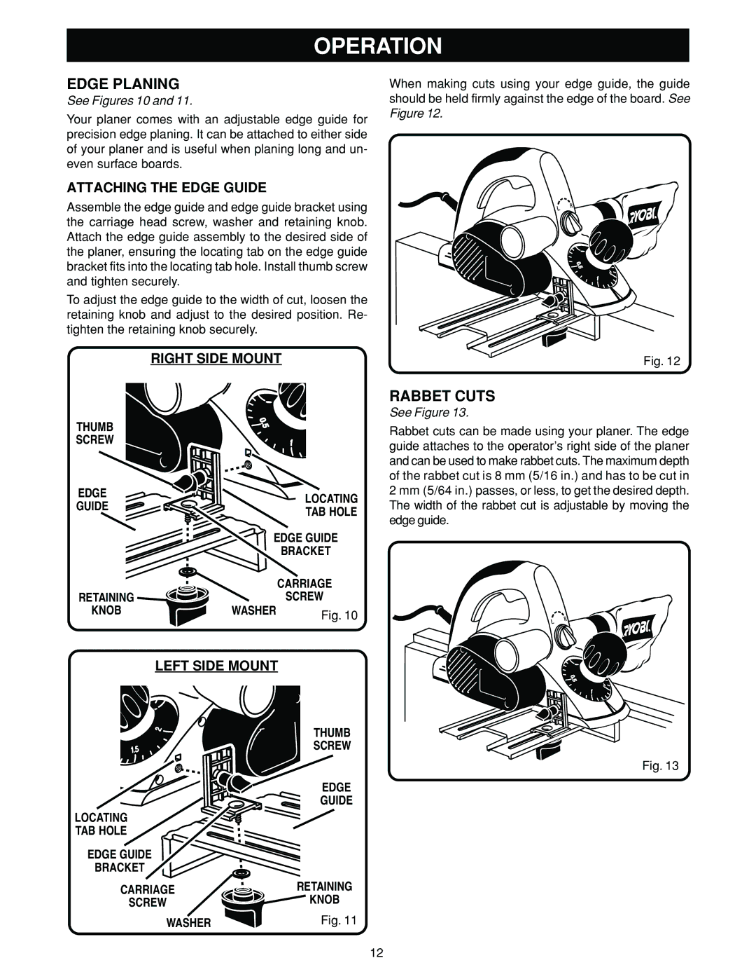
RIGHT SIDE MOUNT
When making cuts using your edge guide, the guide should be held firmly against the edge of the board. See Figure 12.
Fig. 12
THUMB |
|
|
SCREW |
|
|
EDGE |
| LOCATING |
GUIDE |
| |
| TAB HOLE | |
|
| |
| EDGE GUIDE | |
|
| BRACKET |
|
| CARRIAGE |
RETAINING |
| SCREW |
KNOB | WASHER | Fig. 10 |
|
| |
LEFT SIDE MOUNT
THUMB
SCREW
EDGE GUIDE
LOCATING
TAB HOLE
EDGE GUIDE
BRACKET
CARRIAGE | RETAINING |
SCREW | KNOB |
WASHER | Fig. 11 |
RABBET CUTS
See Figure 13.
Rabbet cuts can be made using your planer. The edge guide attaches to the operator’s right side of the planer and can be used to make rabbet cuts. The maximum depth of the rabbet cut is 8 mm (5/16 in.) and has to be cut in 2 mm (5/64 in.) passes, or less, to get the desired depth. The width of the rabbet cut is adjustable by moving the edge guide.
Fig. 13
12