MOUNTING THE ROUTER
WARNING:
Always unplug router and remove router bits before mounting to router table. Remove the fence, the insert, the featherboards and the miter guide from the tabletop before mounting the router.
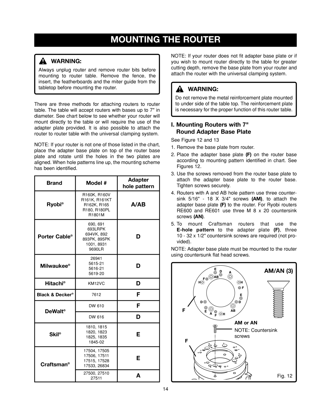
There are three methods for attaching routers to router table. The table will accept routers with bases up to 7" in diameter. See chart below to see whether your router will mount directly to the table or will require the use of the adapter plate provided. It is also possible to attach the router to router table with the universal clamping system.
NOTE: If your router is not one of those listed in the chart, place the adapter base plate on top of the router base plate and rotate until the holes in the two plates are aligned. When hole patterns line up, the mounting scheme has been identified.
Brand | Model # | Adapter | ||
hole pattern | ||||
|
|
| ||
|
|
| ||
| R160K, R160V |
| ||
Ryobi® | R161K, R161KT | A/AB | ||
R162K, R165 | ||||
| R180, R180PL |
| ||
| R1801M |
| ||
|
|
|
| |
| 690, | 691 |
| |
| 693LRPK |
| ||
Porter Cable® | 694VK, 892 | D | ||
893PK, 895PK | ||||
|
| |||
| 1001, | 8931 |
| |
| 9690LR |
| ||
|
|
| ||
| 26941 |
| ||
Milwaukee® | D | |||
|
| |||
|
| |||
|
|
| ||
Hitachi® | KM12VC | D | ||
|
|
| ||
Black & Decker® | 7612 | F | ||
|
|
| ||
DeWalt® | DW 610 | F | ||
|
|
| ||
DW 616 | D | |||
| ||||
|
|
|
| |
| 1810, | 1815 |
| |
Skil® | 1820, | 1823 | E | |
1825, | 1835 | |||
|
| |||
|
| |||
|
|
|
| |
| 17504, | 17505 |
| |
| 17506, 17511 | E | ||
Craftsman® | 17515, | 17528 | ||
| ||||
17533, | 26834 |
| ||
|
|
|
| |
| 27500, | 27510 | A | |
| 27511 | |||
|
| |||
|
|
|
| |
NOTE: If your router does not fit adapter base plate or if you wish to mount router directly to the table for greater cutting depth, remove the base plate from your router and attach the router with the universal clamping system.
WARNING:
Do not remove the metal reinforcement plate mounted to under side of the table top. The reinforcement plate is necessary for the proper function of this router table.
I. Mounting Routers with 7"
Round Adapter Base Plate
See Figure 12 and 13
1.Remove the base plate from router.
2.Place the adapter base plate (F) on the router base according to mounting pattern identified in chart. See Figures 12.
3.Use the screws removed from the router base plate to attach the adapter base plate to the router base. Tighten screws securely.
4.Routers with A and AB hole pattern use three counter- sink 5/16" - 18 X 3/4" screws (AM), to attach the adapter base plate (F) to the router. For Ryobi routers RE600 and RE601 use three M 8 x 20 countersink screws (AN).
5.To mount Craftsman routers that use the
NOTE: Adapter base plate must be mounted to the router using countersunk flat head screws.
AM/AN (3)
F
AM or AN
NOTE: Countersink screws
F
Fig. 12
14
