ASSEMBLY
WARNING:
To prevent accidental starting that could cause serious personal injury, always disconnect the engine spark plug wire from the spark plug when assembling parts.
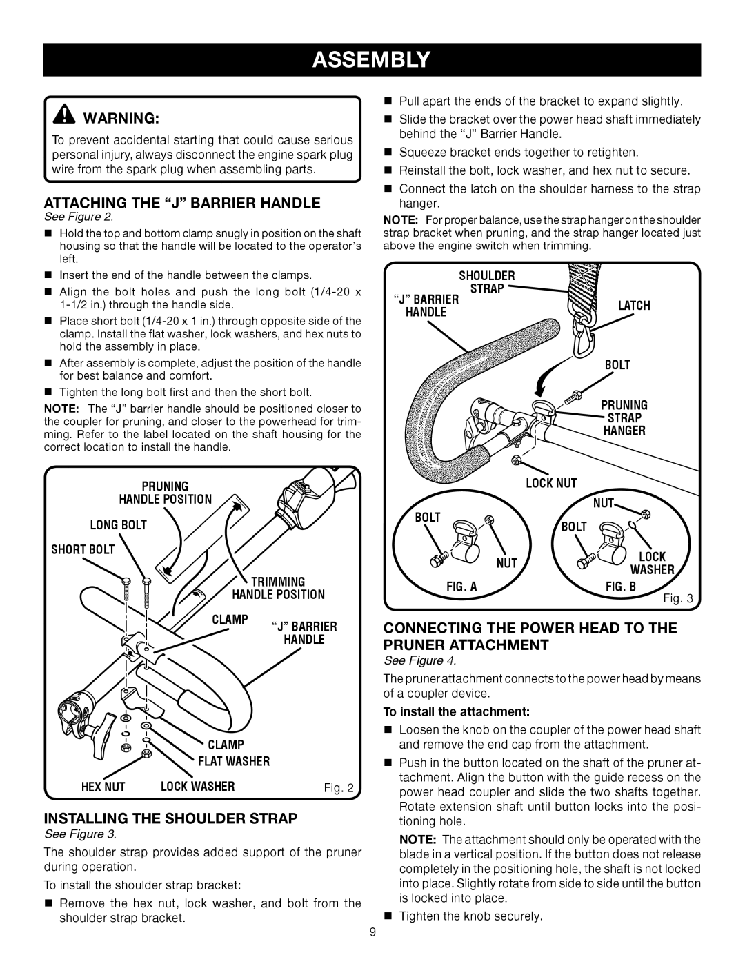
ATTACHING THE “J” BARRIER HANDLE
See Figure 2.
nHold the top and bottom clamp snugly in position on the shaft housing so that the handle will be located to the operator’s left.
nInsert the end of the handle between the clamps.
nAlign the bolt holes and push the long bolt
nPlace short bolt
nAfter assembly is complete, adjust the position of the handle for best balance and comfort.
nTighten the long bolt first and then the short bolt.
NOTE: The “J” barrier handle should be positioned closer to the coupler for pruning, and closer to the powerhead for trim- ming. Refer to the label located on the shaft housing for the correct location to install the handle.
nPull apart the ends of the bracket to expand slightly.
nSlide the bracket over the power head shaft immediately behind the “J” Barrier Handle.
nSqueeze bracket ends together to retighten.
nReinstall the bolt, lock washer, and hex nut to secure.
nConnect the latch on the shoulder harness to the strap hanger.
NOTE: For proper balance, use the strap hanger on the shoulder | ||
strap bracket when pruning, and the strap hanger located just | ||
above the engine switch when trimming. |
| |
| SHOULDER |
|
“J” BARRIER | STRAP |
|
| LATCH | |
HANDLE |
| |
|
| |
|
| BOLT |
|
| PRUNING |
|
| STRAP |
|
| HANGER |
PRUNING
HANDLE POSITION
LONG BOLT
SHORT BOLT
| TRIMMING |
HANDLE POSITION | |
CLAMP | “J” BARRIER |
| |
| HANDLE |
| CLAMP |
|
| FLAT WASHER |
|
HEX NUT | LOCK WASHER | Fig. 2 |
INSTALLING THE SHOULDER STRAP
See Figure 3.
The shoulder strap provides added support of the pruner during operation.
To install the shoulder strap bracket:
nRemove the hex nut, lock washer, and bolt from the
shoulder strap bracket.
LOCK NUT |
| |
BOLT |
| NUT |
BOLT |
| |
|
| |
NUT |
| LOCK |
| WASHER | |
|
| |
FIG. A |
| FIG. B |
|
| Fig. 3 |
CONNECTING THE POWER HEAD TO THE | ||
PRUNER ATTACHMENT |
|
|
See Figure 4. |
|
|
The pruner attachment connects to the power head by means | ||
of a coupler device. |
|
|
To install the attachment: |
|
|
nLoosen the knob on the coupler of the power head shaft and remove the end cap from the attachment.
nPush in the button located on the shaft of the pruner at- tachment. Align the button with the guide recess on the power head coupler and slide the two shafts together. Rotate extension shaft until button locks into the posi- tioning hole.
NOTE: The attachment should only be operated with the blade in a vertical position. If the button does not release completely in the positioning hole, the shaft is not locked into place. Slightly rotate from side to side until the button is locked into place.
nTighten the knob securely.
9