ASSEMBLY
INSTALLING THE WHEEL ASSEMBLY ACCESSORY
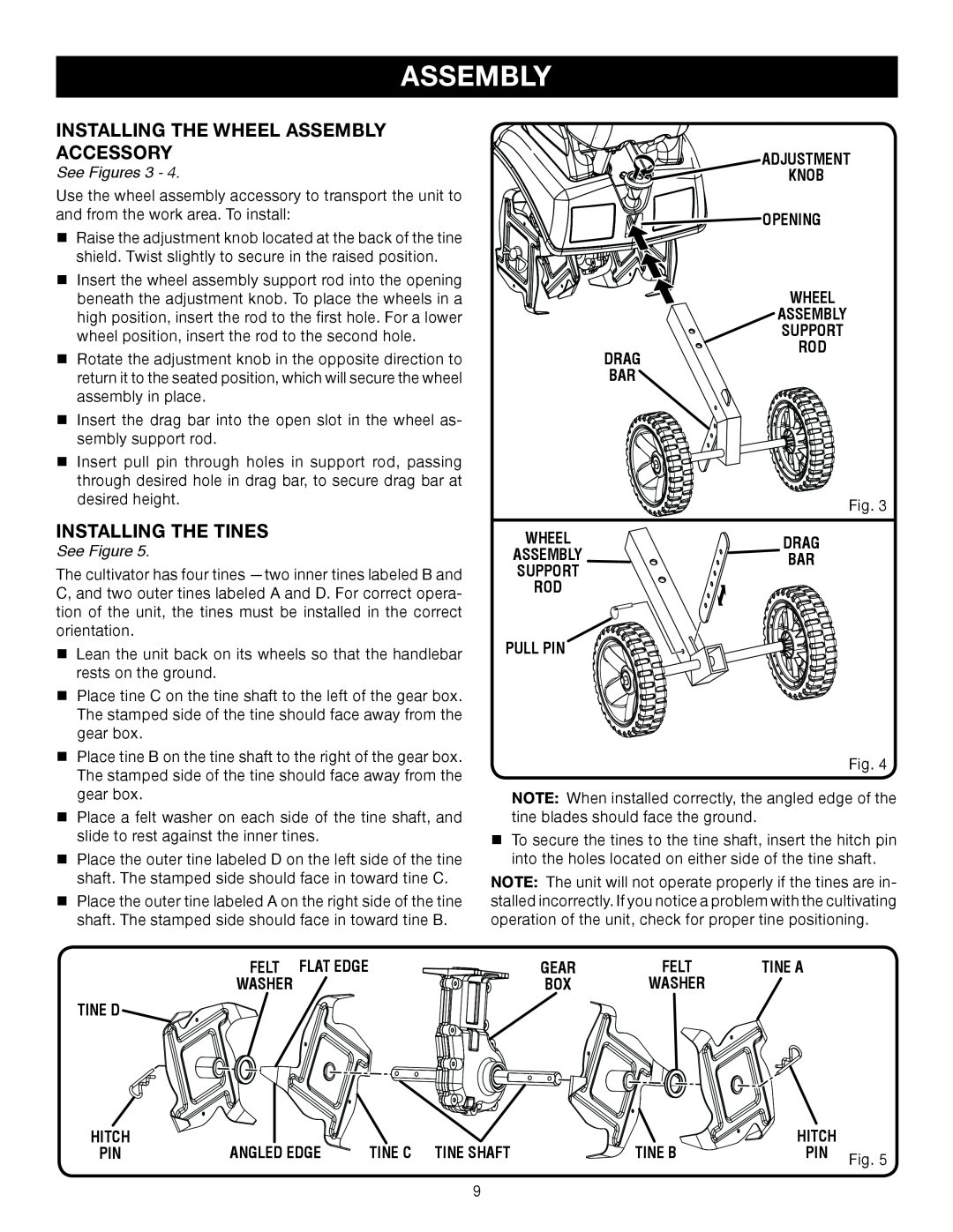
See Figures 3 - 4.
Use the wheel assembly accessory to transport the unit to and from the work area. To install:
n Raise the adjustment knob located at the back of the tine |
shield. Twist slightly to secure in the raised position. |
n Insert the wheel assembly support rod into the opening |
beneath the adjustment knob. To place the wheels in a |
high position, insert the rod to the first hole. For a lower |
wheel position, insert the rod to the second hole. |
ADJUSTMENT
![]()
![]()
![]()
![]()
![]()
![]()
![]()
![]()
![]() KNOB
KNOB ![]()
![]()
![]()
![]() OPENING
OPENING
WHEEL
ASSEMBLY
SUPPORT
n Rotate the adjustment knob in the opposite direction to |
return it to the seated position, which will secure the wheel |
assembly in place. |
n Insert the drag bar into the open slot in the wheel as- |
sembly support rod. |
n Insert pull pin through holes in support rod, passing |
through desired hole in drag bar, to secure drag bar at |
desired height. |
DRAG
BAR
ROD
Fig. 3
INSTALLING THE TINES
See Figure 5.
The cultivator has four tines
nLean the unit back on its wheels so that the handlebar rests on the ground.
nPlace tine C on the tine shaft to the left of the gear box. The stamped side of the tine should face away from the gear box.
nPlace tine B on the tine shaft to the right of the gear box. The stamped side of the tine should face away from the gear box.
nPlace a felt washer on each side of the tine shaft, and slide to rest against the inner tines.
nPlace the outer tine labeled D on the left side of the tine shaft. The stamped side should face in toward tine C.
nPlace the outer tine labeled A on the right side of the tine shaft. The stamped side should face in toward tine B.
FELT FLAT EDGE
WASHER
TINE D
WHEEL | DRAG | |
ASSEMBLY | ||
BAR | ||
SUPPORT | ||
| ||
ROD |
| |
PULL PIN |
|
Fig. 4
NOTE: When installed correctly, the angled edge of the tine blades should face the ground.
nTo secure the tines to the tine shaft, insert the hitch pin into the holes located on either side of the tine shaft.
NOTE: The unit will not operate properly if the tines are in- stalled incorrectly. If you notice a problem with the cultivating operation of the unit, check for proper tine positioning.
GEAR | FELT | TINE A |
BOX | WASHER |
|
HITCH | ANGLED EDGE |
|
| HITCH |
|
PIN | TINE C TINE SHAFT | TINE B | PIN | Fig. 5 | |
|
|
|
|
|
9