Operating the dB500a
Controls and Functions - continued
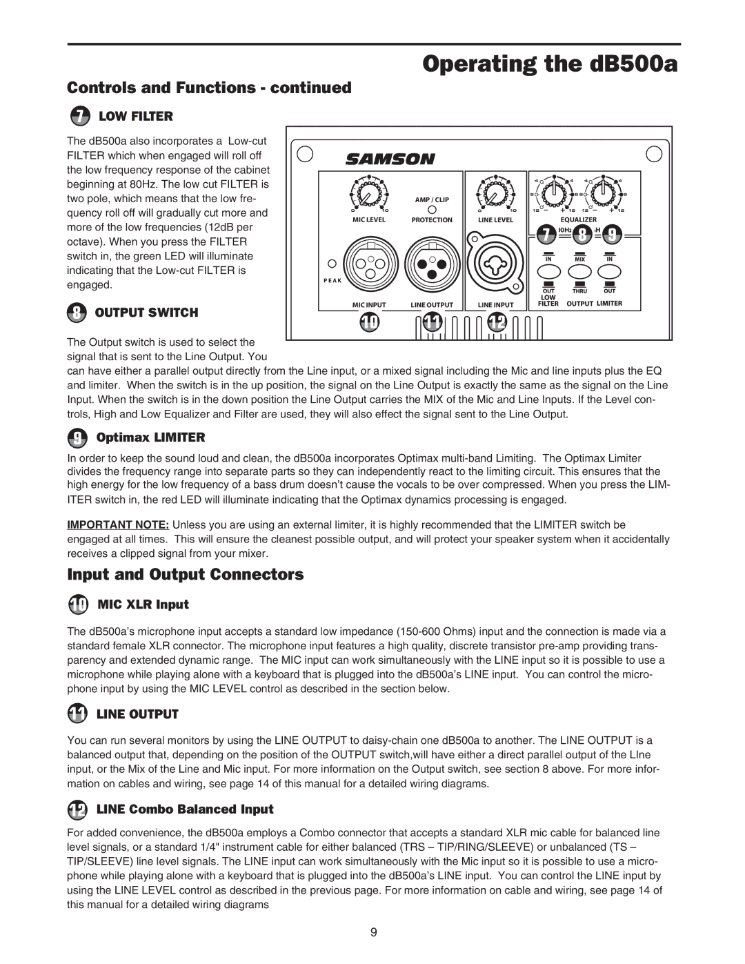
7LOW FILTER
The dB500a also incorporates a |
|
|
|
|
|
|
|
|
| |
FILTER which when engaged will roll off | SAMSON |
|
|
|
|
|
| |||
the low frequency response of the cabinet |
|
|
|
|
|
|
|
|
| |
beginning at 80Hz. The low cut FILTER is |
|
|
|
|
| 4 | 4 | 4 | 4 | |
|
|
|
|
|
|
|
|
| ||
two pole, which means that the low fre- |
|
| AMP / CLIP |
|
| 8 | 8 8 | 8 | ||
|
|
|
|
|
|
|
| |||
quency roll off will gradually cut more and | 0 | 10 |
| 0 | 10 | 12 | 12 | 12 | 12 | |
more of the low frequencies (12dB per | MIC LEVEL | PROTECTION | LINE LEVEL |
| EQUALIZER |
| ||||
|
|
|
|
| LOW 100Hz | HIGH 10KHz | ||||
octave). When you press the FILTER |
|
|
|
|
| 7 |
| 8 | 9 | |
|
|
|
|
|
|
|
|
| ||
switch in, the green LED will illuminate |
|
|
|
|
|
|
|
|
| |
indicating that the |
|
|
|
|
|
|
|
|
| |
engaged. | P E A K |
|
|
|
|
|
|
|
| |
|
|
|
|
|
|
|
|
| ||
8 | OUTPUT SWITCH | MIC INPUT | LINE OUTPUT | LINE INPUT |
|
|
|
| ||
| 10 | 11 |
| 12 |
|
|
|
| ||
|
|
|
|
|
|
|
| |||
The Output switch is used to select the signal that is sent to the Line Output. You
can have either a parallel output directly from the Line input, or a mixed signal including the Mic and line inputs plus the EQ and limiter. When the switch is in the up position, the signal on the Line Output is exactly the same as the signal on the Line Input. When the switch is in the down position the Line Output carries the MIX of the Mic and Line Inputs. If the Level con- trols, High and Low Equalizer and Filter are used, they will also effect the signal sent to the Line Output.
9Optimax LIMITER
In order to keep the sound loud and clean, the dB500a incorporates Optimax
IMPORTANT NOTE: Unless you are using an external limiter, it is highly recommended that the LIMITER switch be engaged at all times. This will ensure the cleanest possible output, and will protect your speaker system when it accidentally receives a clipped signal from your mixer.
Input and Output Connectors
10MIC XLR Input
The dB500a’s microphone input accepts a standard low impedance
11LINE OUTPUT
You can run several monitors by using the LINE OUTPUT to
12LINE Combo Balanced Input
For added convenience, the dB500a employs a Combo connector that accepts a standard XLR mic cable for balanced line level signals, or a standard 1/4" instrument cable for either balanced (TRS – TIP/RING/SLEEVE) or unbalanced (TS – TIP/SLEEVE) line level signals. The LINE input can work simultaneously with the Mic input so it is possible to use a micro- phone while playing alone with a keyboard that is plugged into the dB500a’s LINE input. You can control the LINE input by using the LINE LEVEL control as described in the previous page. For more information on cable and wiring, see page 14 of this manual for a detailed wiring diagrams
9