Guided Tour - Front Panel
� | � | � | � | � | � | � | � | � |
|
|
|
|
|
|
|
| � |
|
|
|
|
|
|
|
| � |
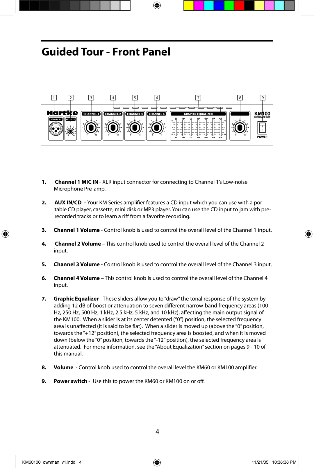
1.Channel 1 MIC IN - XLR input connector for connecting to Channel 1’s
2.AUX IN/CD - Your KM Series amplifier features a CD input which you can use with a por- table CD player, cassette, mini disk or MP3 player. You can use the CD input to jam with pre- recorded tracks or to learn a riff from a favorite recording.
3.Channel 1 Volume - Control knob is used to control the overall level of the Channel 1 input.
4.Channel 2 Volume – This control knob used to control the overall level of the Channel 2 input.
5.Channel 3 Volume - Control knob is used to control the overall level of the Channel 3 input.
6.Channel 4 Volume – This control knob is used to control the overall level of the Channel 4 input.
7.Graphic Equalizer - These sliders allow you to “draw” the tonal response of the system by adding 12 dB of boost or attenuation to seven different
8.Volume - Control knob used to control the overall level the KM60 or KM100 amplifier.
9.Power switch - Use this to power the KM60 or KM100 on or off.
4
KM60100_ownman_v1.indd 4
11/21/05 10:38:38 PM ![]()