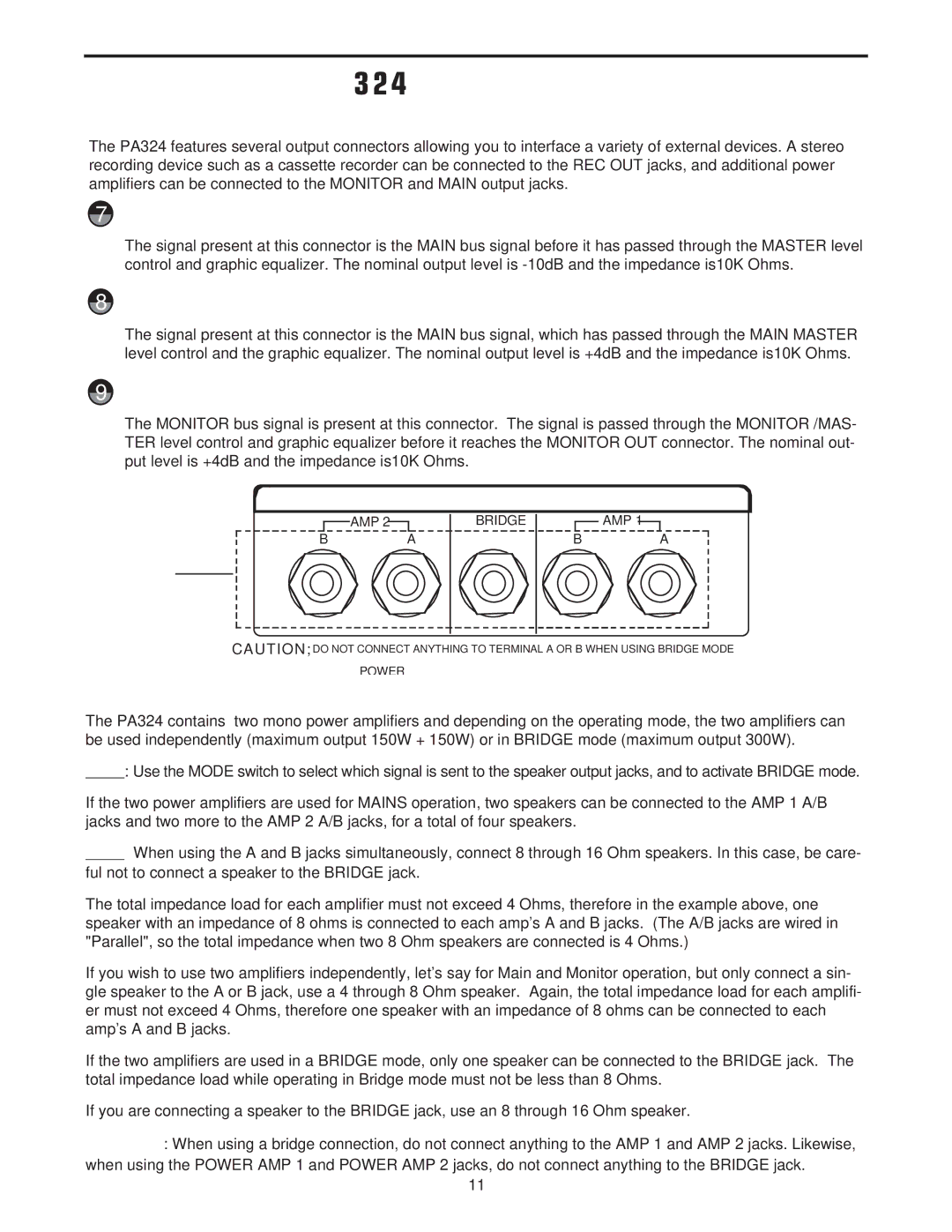
PA324 specifications
The Samson PA324 is a powerful and versatile audio mixer designed for both professional and amateur sound engineers. This compact device boasts a range of features that make it suitable for various applications including live performances, studio recordings, and broadcasting.One of the standout characteristics of the PA324 is its impressive number of inputs. With a total of 24 channels, the mixer accommodates multiple microphones, instruments, and other audio sources, enabling users to mix various signals seamlessly. The PA324 supports both XLR and 1/4-inch TRS connections, providing flexibility and convenience when connecting different devices.
The mixer incorporates high-quality preamps that deliver clean and transparent audio. This is especially important for professional applications where sound clarity is paramount. Users can expect minimal noise and distortion, even when pushing the gain levels. Additionally, the PA324 features a 3-band EQ on each channel, allowing for precise tonal adjustments to tailor the sound to the environment or personal preference.
For added versatility, the PA324 includes built-in digital effects. These effects range from reverbs to delays, enhancing the overall audio experience without the need for external processors. The intuitive interface makes it easy for users to apply and fine-tune these effects on the fly.
Another key feature of the PA324 is its onboard USB interface, which enables direct connection to computers for streaming and recording. This feature is particularly beneficial for podcasters and content creators looking to capture high-quality audio without the hassle of external recording devices.
The mixer is also built for durability, featuring a solid metal chassis that can withstand the rigors of travel and live sound applications. The design includes a clear and accessible layout, making it user-friendly even for those new to audio mixing.
Overall, the Samson PA324 is an exceptional audio mixer that combines robust performance and user-friendly technology. Its extensive input options, quality preamps, integrated effects, and USB connectivity make it an ideal choice for a wide range of audio applications, ensuring that it meets the needs of sound engineers and musicians alike. Whether in a studio or on stage, the PA324 is designed to deliver outstanding audio performance.

