Installing the Camera
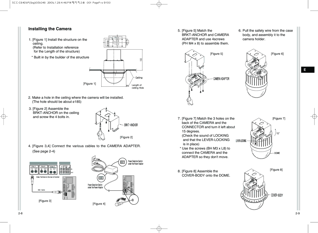
1.[Figure 1] Install the structure on the ceiling.
(Refer to Installation reference for the Length of the structure)
*Built in by the builder of the structure
5. [Figure 5] Match the | 6. Pull the safety wire from the case |
body, and assembly it to the | |
ADAPTER and use 4screws | camera holder. |
(PH M4 x 8) to assemble them. |
|
[Figure 5] | [Figure 6] |
E
[Figure 1]
2.Make a hole in the ceiling where the camera will be installed. (The hole should be about ø185)
3.[Figure 2] Assemble the BRKT-ANCHOR on the ceiling and screw the 4 bolts in.
Length of ceiling Hole
7.[Figure 7] Match the 3 holes on the back of the CAMERA and the CONNECTOR and turn it left about 15 degrees.
[Figure 7]
[Figure 2]
4.[Figure 3,4] Connect the various cables to the CAMERA ADAPTER. (See page 2-4)
[Figure 3]
[Figure 4]
(Check the sound of LOCKING and that the LEVER-LOCKING is in place)
*Use the screws (BH M3 x L8) to connect the CAMERA and the ADAPTER so they don't move.
8.[Figure 8] Assemble the COVER-BODY onto the DOME.
[Figure 8]