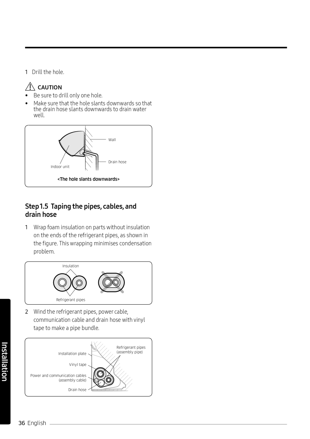
QUESTIONS OR COMMENTS
Usermanual/Installation manual
AR✴✴KRJS✴✴, AR✴✴KQJS✴✴, AR✴✴MRJS✴✴, AR✴✴MQJS✴✴
DB68-06070A-01
Contents
Safety Information
At a Glance
Power Smart Features
Energy-SavingFeatures
Indoor Unit Installation
Step 2.1 Disassembling the cover panel
Disassembling the installation plate
Connecting the cables (assembly cable)
Optional: Extending the power cable
Safety Information
FOR INSTALLATION
FOR POWER SUPPLY
•Do not use a ventilating fan
•A spark may result in an explosion or fire
To reinstall the air conditioner, please contact your nearest service centre
Do not touch the circuit breakerwith wet hands
•This may result in electric shock
•Water dripping from the indoor unit may result in fire or property damage
•Failing to do so may result in injury, death or property damage
•This may result in electric shock, fire, problems with the product, or injury
Do not operate the appliance with wet hands
•The water may be harmful to humans
Page
Indoor Unit Overview
Glance a At
Remote Control Overview
Remote Control Operation
Controlling fan speed
Controlling airflow direction
Cooling Operation
Features Smart Power
Dehumidifying Operation
Heating Operation
Quick Smart Features
Fast function
Comfort function
Beep sound function
Energy-SavingOperation
Features Saving-Energy
Timed on/Timed off function
good’sleep function
In the Cool or Heat mode ►
(Select
among
On, Off, and .)
Cleaning at a Glance
Running Auto clean
Cleaning the indoor unit exterior and outdoor unit heat exterior
Cleaning the filter
Troubleshooting
• When the Auto, Dry, or Fast mode is running or the good'sleep function
is running in the Cool mode, the air conditioner controls the fan speed
fan speed
automatically and you cannot change the fan speed
• Replace the batteries in the remote control with new ones
Technical Specifications
AR24KRJSRWK/MG
Page
AR24MRJSRWK/MG
Safety Information on Installation
Installation
General information
Installation of the unit
Power supply line, fuse, or circuit breaker
Preparation
Step1.1 Choosing the installation location
Step1.2 Packing and Unpacking
indoor unit
Outdoor unit
Page
Accessories in the outdoor unit package
Tools
General tools
•Vacuum pump
(Backward flowing prevention)
Step1.5 Taping the pipes, cables, and drain hose
Indoor Unit Installation
Step 2.3 Connecting the cables (assembly cable)
•Tighten the terminal block screw to 1.2-1.8N•m (1.2-1.8kgf•cm)
•Each wire is labelled with the corresponding terminal number
•Use shield cable (Category 5; less than 50pF/m) for noisy environmental site
•Power & Communication cable shall not exceed 30m
Step 2.4 Optional: Extending the power cable
1Prepare the following tools
•Peel off 20 mm of the wire shields from the preinstalled tube
•After peeling off the tube wire, you must insert a contraction tube
•The compression dimension should be
––Incomplete wire
Step 2.5 Installing and connecting the drain hose
1Install the drain hose
2Pour water into the drain pan. Check whether the hose is well drained
•Inadequate installation may cause water leakage
Step 2.7 Optional: Changing the direction of the drain hose
There are 2 refrigerant pipes of different diameters:
•The smaller one is for the liquid refrigerant
•The larger one is for the gas refrigerant
Step 2.9 Shortening or extending the refrigerant pipes (assembly pipe)
Step 2.10 Fixing the installation plate
You can install the indoor unit on a wall, window frame, or gypsum board
Tighten the flare nut at the specified torque. If the flare nut is
When fixing the indoor unit on a wall
When fixing the indoor unit on a window frame
1Use stud finder to find out locations of the studs
2Fix the plate hanger on two studs
•Fix the installation plate without inclining to one side
Step 2.11 Fixing the indoor unit to the installation plate
Step 2.12 Assembling the cover panel
Outdoor Unit Installation
Step 3.1 Fixing the outdoor unit in place
1Leave the system in the standby mode
Step 3.3 Evacuating the air
of cooling capacity and malfunction. Use a vacuum pump
3Open the valve of the low pressure side of manifold gauge anticlockwise
•Close the valve of the low pressure side of manifold gauge clockwise
•Turn off the vacuum pump
•Check for 2 minutes if there is any pressure change
•Remove the hose of the low pressure side of manifold gauge
Installation Inspection
Page
Step 4.3 Performing final check and trial operation
1Check the following:
•Strength of the installation site
•Electric wiring connection
•Heat-resistantinsulation of the pipe