DSB-4700F
DESCRIPTION
![]()
![]()
![]() Front
Front![]()
![]() Panel
Panel![]()
![]()
![]()
![]()
![]()
![]()
![]()
![]()
![]()
![]()
![]()
![]()
![]()
![]()
![]()
![]()
![]()
![]()
![]()
DESCRIPTION


 Rear
Rear
 Panel
Panel


DSB-4700F
| 1 | 2 | 3 | 4 | 5 | 6 | |
1. |
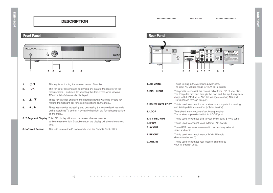
| / I | This key is for turning the receiver on and Standby. | ||||
| |||||||
| |||||||
2. | OK | This key is for entering and confirming any data to the receiver in the | |||||
|
|
| menu system. This key is for selecting the item. Press while viewing | ||||
|
|
| TV and a list of channels is displayed. | ||||
3. | … , † | These keys are for changing the channels during watching TV and for | |||||
|
|
| moving the highlight bar for selecting options on the menu. | ||||
4. | œ , √ | These keys are for increasing and decreasing the volume level manually | |||||
|
|
| during watching TV and for moving the highlight bar for selecting options | ||||
|
|
| on the menu. |
|
| ||
5.7 Segment Display This LED display will show the current channel number.
While the receiver is in Standby mode, the display will show the current time.
6.Infrared Sensor This is to receive the IR commands from the Remote Control Unit.
1 | 2 | 3 | 4 | 5 | 6 | 7 | 8 | 9 |
1. | AC MAINS | This is to plug in the AC mains power cord. |
|
| The input AC voltage range is 120V, 60Hz supply. |
2. | DISH INPUT | This port is to connect the coaxial cable from LNB of your dish. |
|
| The IF input is provided through this port and the input frequency |
|
| range is |
|
| 18V is passed through this port. |
3.RS 232 DATA PORT This is used to connect your receiver to a computer for reading and loading data information. (only for service)
4. LOOP | To enable the connection of an Analog receiver, |
| The receiver is provided with this ‘LOOP’ port. |
5.
6. | 0/12V | This is used to connect to an external LNB switch. |
7. | AV OUT | These RCA connectors are used to connect any external |
|
| video and audio. |
8. | RF OUT | This is used to connect to your TV via RF cable. |
|
| (Preset to channel 3) |
9. | ANT. IN | This is used to connect your local RF channels to |
|
| your TV through Loop. |
10 | D I G I T A L | S A T E L L I T E | R E C E I V E R | 11 |