Installing the hob
Installing the hob
Connecting to the mains power supply
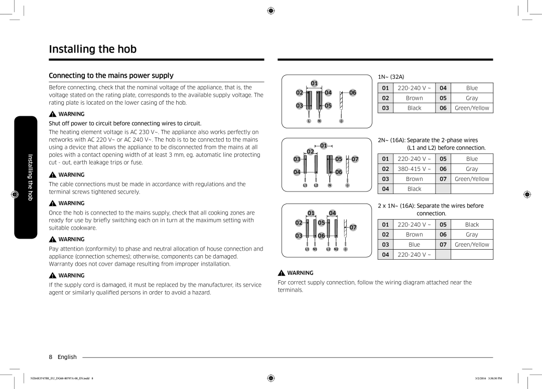
Before connecting, check that the nominal voltage of the appliance, that is, the voltage stated on the rating plate, corresponds to the available supply voltage. The rating plate is located on the lower casing of the hob.
![]() WARNING
WARNING
Shut off power to circuit before connecting wires to circuit.
The heating element voltage is AC 230 V~. The appliance also works perfectly on networks with AC 220 V~ or AC 240 V~. The hob is to be connected to the mains using a device that allows the appliance to be disconnected from the mains at all poles with a contact opening width of at least 3 mm, eg. automatic line protecting cut - out, earth leakage trips or fuse.
![]() WARNING
WARNING
The cable connections must be made in accordance with regulations and the terminal screws tightened securely.
![]() WARNING
WARNING
Once the hob is connected to the mains supply, check that all cooking zones are ready for use by briefly switching each on in turn at the maximum setting with suitable cookware.
![]() WARNING
WARNING
Pay attention (conformity) to phase and neutral allocation of house connection and appliance (connection schemes); otherwise, components can be damaged. Warranty does not cover damage resulting from improper installation.
01
02![]()
![]() 04
04 ![]() 06
06
03![]()
![]() 05
05
L N
01 ![]()
02
03 | 05 | 07 |
04![]()
![]() 06
06
L1 L2 N
01 |
| 04 |
|
|
|
| |||||||
02 |
|
|
|
| 05 |
|
|
|
|
|
|
| |
|
|
|
|
|
|
|
|
|
| 07 | |||
|
|
|
|
|
|
|
|
|
| ||||
03 |
|
|
|
| 06 |
|
|
|
|
|
| ||
|
|
|
|
|
|
|
| ||||||
|
|
|
|
|
|
|
|
|
|
| |||
|
|
|
|
|
|
|
|
|
|
| |||
|
|
|
|
|
|
|
|
|
|
|
|
|
|
|
|
|
|
|
|
|
|
|
|
|
|
|
|
| L1 | N1 |
|
| L2 | N2 | |||||||
1N~ (32A)
01 | 04 | Blue | |
02 | Brown | 05 | Gray |
|
|
|
|
03 | Black | 06 | Green/Yellow |
|
|
|
|
2N~ (16A): Separate the
(L1 and L2) before connection.
01 | 05 | Blue | |
02 | 06 | Gray | |
03 | Brown | 07 | Green/Yellow |
04Black
2 x 1N~ (16A): Separate the wires before
connection.
01 | 05 | Black | |
02 | Brown | 06 | Gray |
|
|
|
|
03 | Blue | 07 | Green/Yellow |
04
![]() WARNING
WARNING
If the supply cord is damaged, it must be replaced by the manufacturer, its service agent or similarly qualified persons in order to avoid a hazard.
8 English
![]() WARNING
WARNING
For correct supply connection, follow the wiring diagram attached near the terminals.
3/2/2016 3:38:30 PM
