OPERATION PRINCIPLES BY PARTS OF CIRCUIT
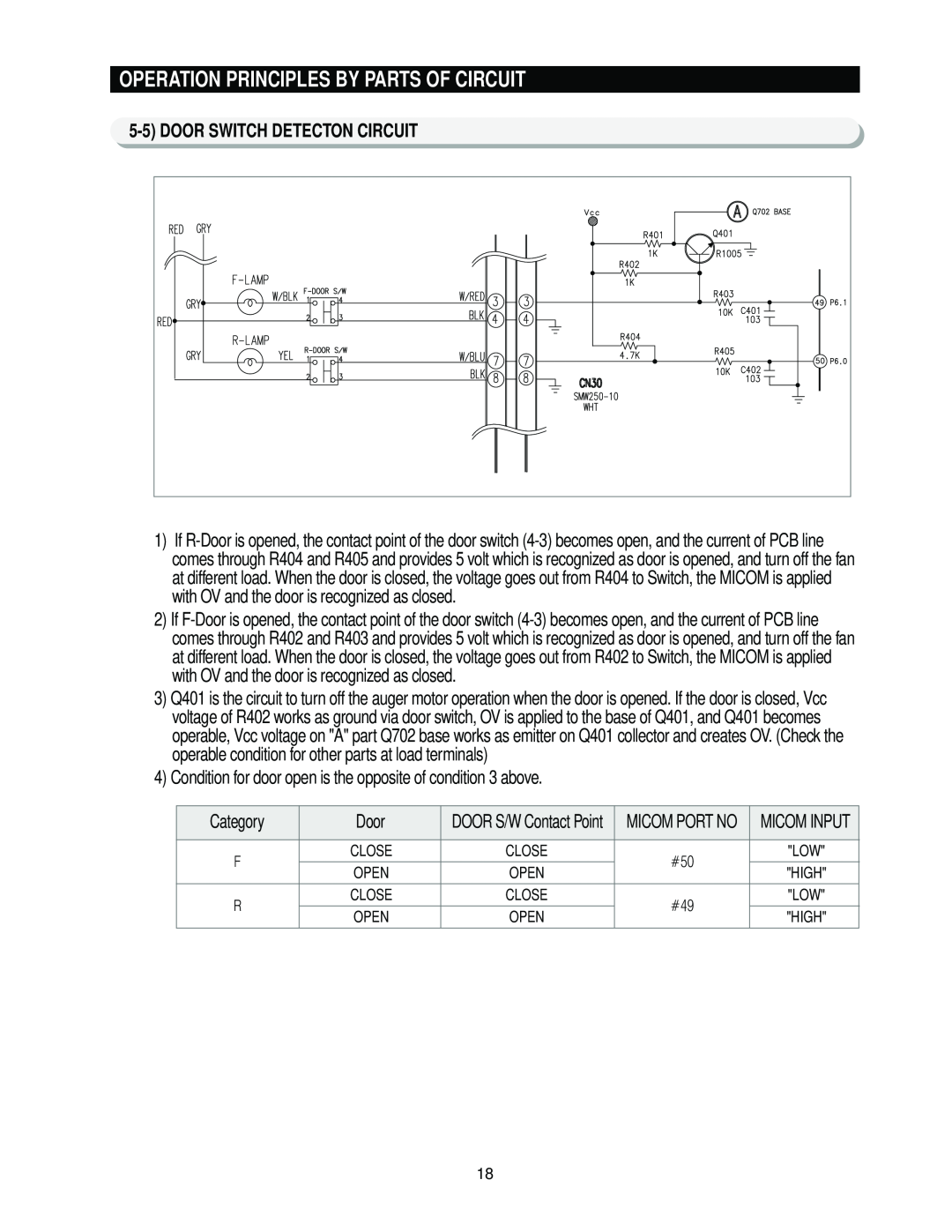
5-5) DOOR SWITCH DETECTON CIRCUIT
1)If
2)If
3)Q401 is the circuit to turn off the auger motor operation when the door is opened. If the door is closed, Vcc voltage of R402 works as ground via door switch, OV is applied to the base of Q401, and Q401 becomes operable, Vcc voltage on "A" part Q702 base works as emitter on Q401 collector and creates OV. (Check the operable condition for other parts at load terminals)
4)Condition for door open is the opposite of condition 3 above.
Category | Door | DOOR S/W Contact Point | MICOM PORT NO | MICOM INPUT | |
|
|
|
|
| |
F | CLOSE | CLOSE | #50 | "LOW" | |
OPEN | OPEN | "HIGH" | |||
|
| ||||
R | CLOSE | CLOSE | #49 | "LOW" | |
|
|
| |||
OPEN | OPEN | "HIGH" | |||
|
| ||||
|
|
|
|
|
18