Appendix Ⅰ(Reference for circuit diagnostics)
Turn on Power and check status of Relay & Driving Circuit by checking followings according to load operation.
LOAD | RELAY | TERMINALS | VALUE | WHEN IT IS DIFFERENT FROM MEASURED VALUE | ||
|
|
|
|
|
| |
|
| RY76 /RY75 | CN71⑪∼⑨ | SUPPLY | RY76 CONTACT SHORT,FAULTY DRIVING CIRCUIT | |
DEFROST / COMP OFF | VOLTAGE(SV) | |||||
|
| RY75 | CN71⑬∼⑨ | SV | RY75 NO CONTACT SHORT,FAULTY DRIVING CIRCUIT | |
|
| RY76 /RY75 | CN71⑪∼⑨ | SV | FAULTY RY75 / | |
COMP ON | RY76 NO CONTACT SHORT,FAULTY DRIVING CIRCUIT | |||||
|
|
| ||||
|
| RY75 | CN71⑬∼⑨ | 0V | RY75 NO CONTACT OPEN, FAULTY DRIVING CIRCUIT | |
|
| RY76 /RY75 | CN71⑪∼⑨ | 0V | FAULTY RY76 / | |
DEFROST | RY75 NC CONTACT OPEN, FAULTY DRIVING CIRCUIT | |||||
|
|
| ||||
|
| RY75 | CN71⑬∼⑨ | SV | RY75 NO CONTACT SHORT,FAULTY DRIVING CIRCUIT | |
|
|
|
|
| ||
CUBE & AUGER | RY73 /RY74 | CN71⑨∼CN70③ | SV | RY73 &RY74 NO CONTACT SHORT,FAULTY DRIVING CIRCUIT | ||
MOTOR OFF |
| RY74 | CN71⑨∼CN70① | SV | RY74 NO CONTACT SHORT,FAULTY DRIVING CIRCUIT | |
|
|
|
|
| ||
CUBE & AUGER | RY73 /RY74 | CN71⑨∼CN70③ | 0V | RY73 OR RY74 NO CONTACT OPEN, FAULTY DRIVING CIRCUIT | ||
MOTOR OPERATING | RY74 | CN71⑨∼CN70① | 0V | RY74 NO CONTACT OPEN, FAULTY DRIVING CIRCUIT | ||
F FAN ON | RY79 | CN71①∼⑨ | 0V | RY79 NO CONTACT OPEN, FAULTY DRIVING CIRCUIT | ||
C FAN ON | RY77 | CN71⑦∼⑨ | 0V | RY77 NO CONTACT OPEN, FAULTY DRIVING CIRCUIT | ||
WATER VALVE | RY71 | CN71⑨∼CN70⑦ | 0V | RY71 NO CONTACT OPEN, FAULTY DRIVING CIRCUIT | ||
DISPENSER OPERATING | ||||||
|
|
|
| |||
|
|
|
|
| ||
WATER VALVE ICE | RY72 | CN71⑨∼CN70⑤ | 0V | RY72 NO CONTACT OPEN, FAULTY DRIVING CIRCUIT | ||
MAKER OPERATING | ||||||
|
|
|
| |||
|
|
|
|
|
| |
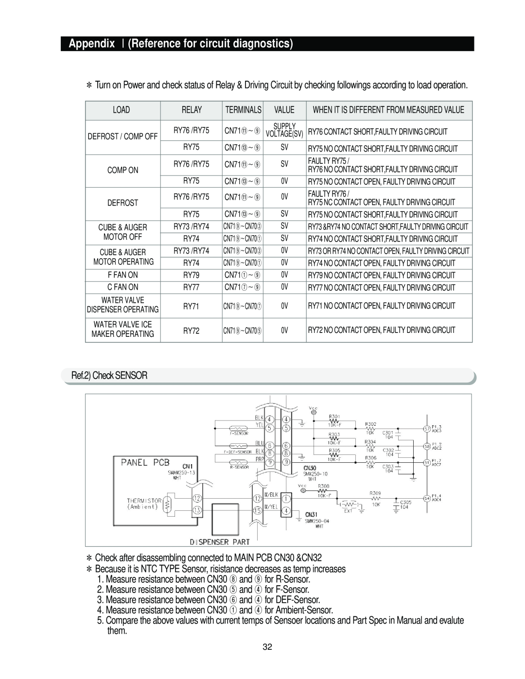
Ref.2) Check SENSOR
Check after disassembling connected to MAIN PCB CN30 &CN32
Because it is NTC TYPE Sensor, risistance decreases as temp increases
1.Measure resistance between CN30 ⑧ and ⑨ for
2.Measure resistance between CN30 ⑤ and ④ for
3.Measure resistance between CN30 ⑥ and ④ for
4.Measure resistance between CN30 ① and ④ for
5.Compare the above values with current temps of Sensoer locations and Part Spec in Manual and evalute them.
32