FLOPPY DISK DRIVE SPECIFICATION
PAGE | 18 |
|
|
MODEL |
|
|
|
5.3.3 Motor On
Logical "LOW" level of this signal makes the spindle motor be turned on. The motor reaches to the rated rotational speed within 500 ms after this signal changes to "LOW".
This input signal is ignored when no disk is installed.
5.3.4 Direction Select
This signal specifies the moving direction of the R/W head when the Step input is activated.
Logical "LOW" level : the direction to the inner tracks of a disk. "HIGH" level : the direction to the outer tracks of a disk.
5.3.5 Step
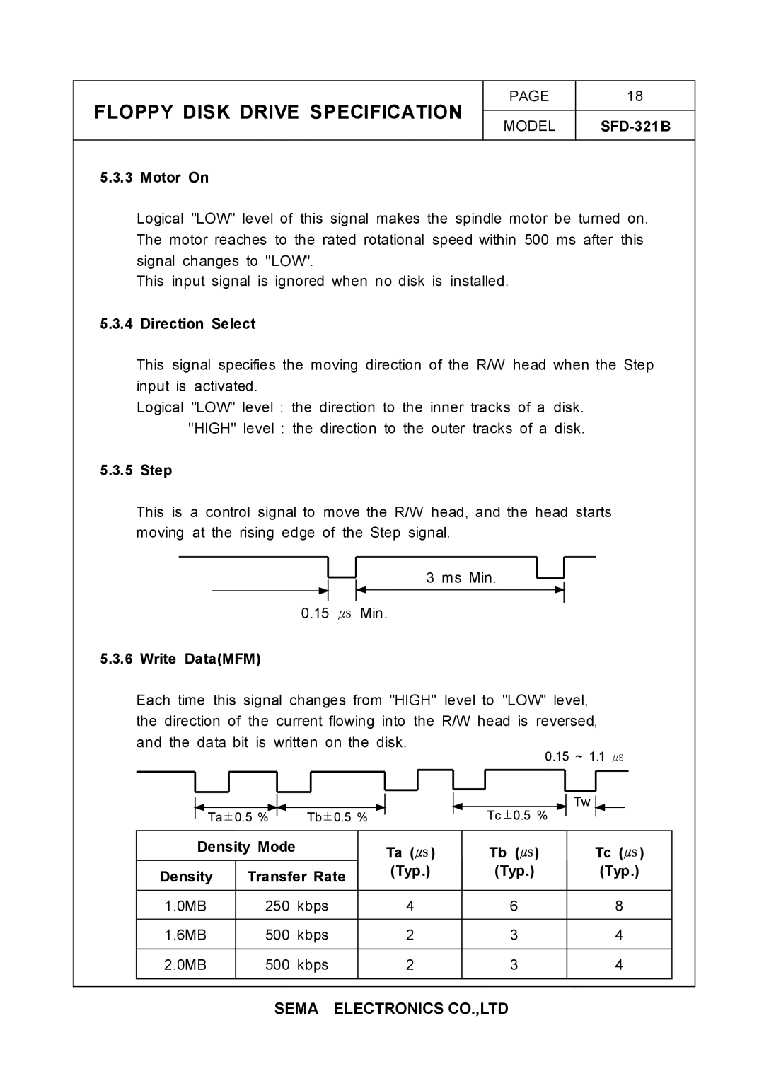
This is a control signal to move the R/W head, and the head starts moving at the rising edge of the Step signal.
3 ms Min.
0.15 ㎲ Min.
5.3.6 Write Data(MFM)
Each time this signal changes from "HIGH" level to "LOW" level, the direction of the current flowing into the R/W head is reversed, and the data bit is written on the disk.
Ta±0.5 %
Tb±0.5 %
0.15 ~ 1.1 ㎲
Tw
Tc±0.5 %
Density Mode |
| Ta | ( | ㎲ | ) | ㎲ | ㎲ | |
|
|
|
| Tb ( ) | Tc ( ) | |||
Density | Transfer Rate | (Typ.) |
| (Typ.) | (Typ.) | |||
|
|
|
|
|
| |||
|
|
|
|
|
|
|
|
|
1.0MB | 250 | kbps |
| 4 |
|
| 6 | 8 |
|
|
|
|
|
|
|
|
|
1.6MB | 500 | kbps |
| 2 |
|
| 3 | 4 |
|
|
|
|
|
|
|
|
|
2.0MB | 500 | kbps |
| 2 |
|
| 3 | 4 |
|
|
|
|
|
|
|
|
|
SEMA ELECTRONICS CO.,LTD
