Name and Function of Each Section
![]() Pan Base Holding Screws (Color : Silver)
Pan Base Holding Screws (Color : Silver)
fix panned position
![]() Zoom Handle
Zoom Handle
adjust zoom between WIDE and TELE
![]() Focus Handle
Focus Handle
after adjusting zoom, adjust focus
![]() SETUP button
SETUP button
Used for the menu display. Confirm the status of the selected function.
![]() Left button
Left button ![]() Right button
Right button
Installation
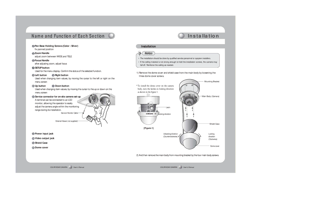
Installation
Notes
•The installation should be done by qualified service personnel or sysytem installers.
•If the ceiling material is not strong enough to hold the installation screws, the camera may fall off. Reinforce the ceiling as needed.
1)Remove the dome cover and shield case from the main body by loosening the three dome cover screws.
Used when changing item values, by moving the cursor to the left or right on the menu screen
Up button | Down button |
Used when changing item values, by moving the cursor to the up or down on the menu screen
![]() Service connector for
Service connector for
*To install the dome cover on the camera body, turn the latches in locking direction as shown in the figure 1.
Mounting Bracket
Main Body (Camera) |
adjust the camera angle within the monitoring range during its installation.
Service/ Monitor Cable![]()
External Viewer (not supplied)
 Power input jack
 Video output jack
 Shield Case
 Dome cover
COLOR DOME CAMERA 12 User’s Manual
Latch
Locking direction
| Shield Case |
| |
Unlocking direction | Locking |
(Counterclockwise) | direction |
| (Clockwise) |
| Dome cover |
2) And then remove the main body from mounting bracket by the four main body screws.
COLOR DOME CAMERA 13 User’s Manual