Connection
Connecting to a Monitor | Connecting to Power |
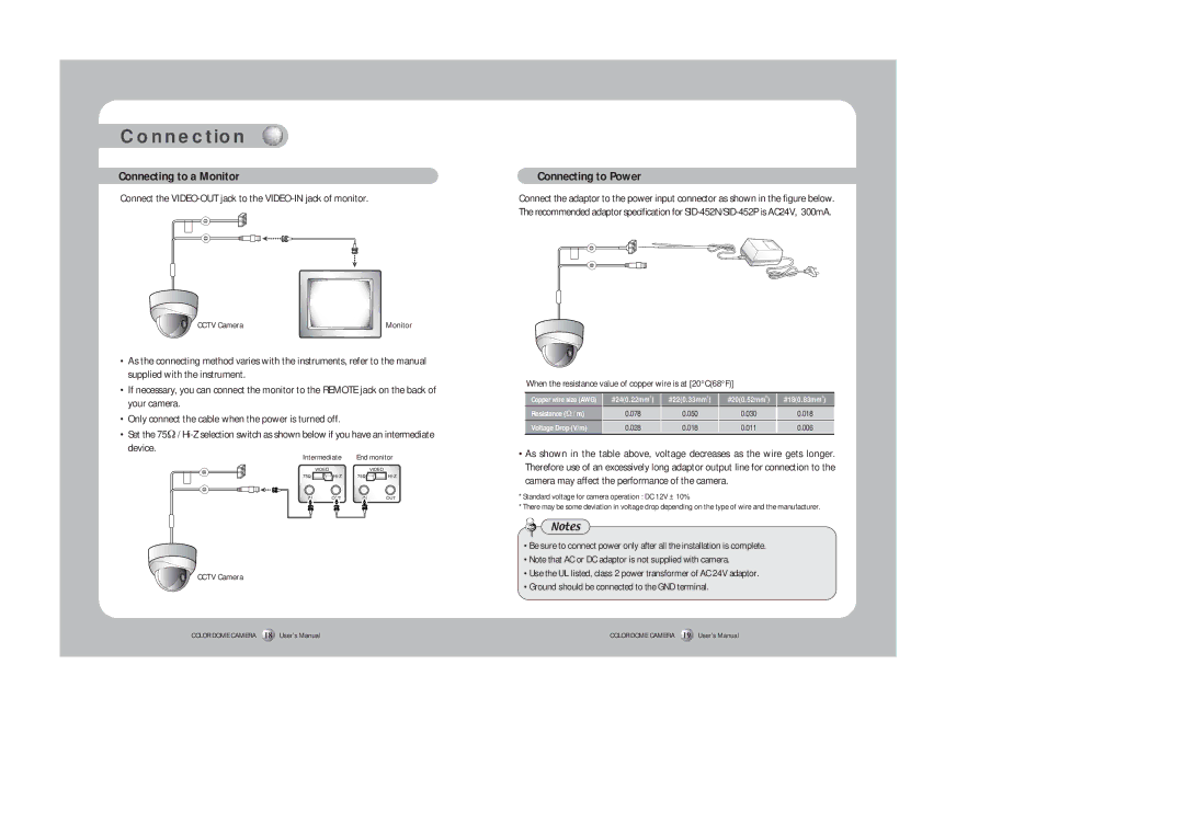
Connect the VIDEO-OUT jack to the VIDEO-IN jack of monitor.
Connect the adaptor to the power input connector as shown in the figure below. The recommended adaptor specification for
CCTV Camera | Monitor |
•As the connecting method varies with the instruments, refer to the manual supplied with the instrument.
•If necessary, you can connect the monitor to the REMOTE jack on the back of your camera.
•Only connect the cable when the power is turned off.
•Set the 75Ω /
Intermediate | End monitor |
CCTV Camera
COLOR DOME CAMERA 18 User’s Manual
When the resistance value of copper wire is at [20°C(68°F)]
Copper wire size (AWG) | #24(0.22mm2) | #22(0.33mm2) | #20(0.52mm2) | #18(0.83mm2) |
Resistance (Ω / m) | 0.078 | 0.050 | 0.030 | 0.018 |
Voltage Drop (V/m) | 0.028 | 0.018 | 0.011 | 0.006 |
•As shown in the table above, voltage decreases as the wire gets longer. Therefore use of an excessively long adaptor output line for connection to the camera may affect the performance of the camera.
*Standard voltage for camera operation : DC 12V ± 10%
*There may be some deviation in voltage drop depending on the type of wire and the manufacturer.
Notes
•Be sure to connect power only after all the installation is complete.
•Note that AC or DC adaptor is not supplied with camera.
•Use the UL listed, class 2 power transformer of AC 24V adaptor.
•Ground should be connected to the GND terminal.
COLOR DOME CAMERA 19 User’s Manual