Quick Guide
WHAT’S Included
Product Introduction
Main Board
Quick Guide Diode UF4004, 1N4001~4007
Power LED Indicator
Board ID Setup Switch
Output LED Indicator
Host computer
Board
Input LED Indicator
Input Ports Input ports #1 ~ #7 Input #1 ~ #7 Fixing Hole
Buzzer
Input port #9
Input port #8
Input port #10
Input port #11
Power Connection
POWER, READER, and I/O Connection
Reader Connection
Door Number
Exit Button
Connect the other line NC of the door sensor to GND
Input Connection
Connect the minus line of the alarm device to GND
Connect the COM line of the alarm device relay to DC +12V
Door Number Door Lock Alarm Device
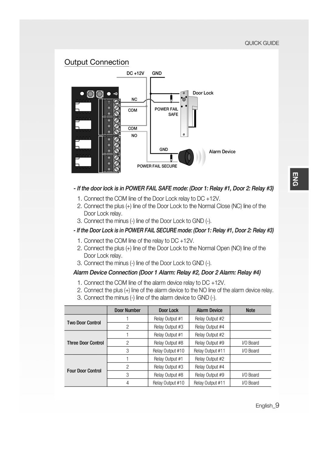
Output Connection
Communication Line Connection
RS-232 Communication Port Connection
Check the location of the communication port
RS-422 Communication Port Connection Standalone
RxD TxD Power
RS-232C
MAX m
RS-422 Communication Port Connection Multiple Units
TCP/IP Communication Port Connection
TCP/IP Communication Configuration
TCP/IP Connection
On the upper Initialize Switch
Initializing the system using the Initialize switch
Initialization
System Initialization
Board ID Setting
Refer to the example below for the board ID
Example
AB82-02548A
Guide de prise en main rapide
Contenu
Lancement du produit
Carte mère
Guide de prise en main rapide Diode UF4004, 1N4001~4007
Utilisé pour les communications avec l’ordinateur hôte
’ID de carte
Interrupteur d’initialisation
Système
Carte E/S
Mère
Connecteur utilisé pour la connexion à la carte mère
Port de sortie n10 FORM-C
Port de sortie n11 FORM-C
Installation et connexion externe
ALIMENTATION, Lecteur ET Connexion E/S
Branchement de l’alimentation
Connexion du lecteur
Commande à
Bouton de sortie
Portes
Connexion d’entrée
Connectez l’autre ligne NC du capteur de porte à GND
Remarque
Connexion de sortie
Connectez la ligne moins du dispositif d’alarme à GND
Branchez la ligne COM du relais sur CC+12
Dispositif de
Vérifiez l’emplacement du port de communication
Installez l’application Sams et lancez-la
Connexion DES Lignes DE Communication
Connexion du port de communication RS-232
Connexion du port de communication RS-422 mode autonome
RxD TxD Alimentation
MAX 200 m
Spécifi ez un ID de carte unique pour chaque produit
Connexion du port de communication RS-422 unités multiples
Connexion du port de communication TCP/IP
Configuration de la communication TCP/IP
Connexion TCP/IP
Initialisation DU Système
Initialisation
Interrupteur
Localisez l’interrupteur d’initialisation
Réglage DE L’ID DE Carte
Reportez-vous à l’exemple de l’ID de carte ci-dessous
Exemple
AB82-02548A
Kurzanleitung
Lieferumfang
Produkteinführung
Hauptplatine Mainboard
Kurzanleitung Diode 12 Stk UF4004, 1N4001~4007
Anschluss E/A-Board
Board-ID Setup-Schalter
Nach der Initialisierung neu gestartet
Nr Relais Nr DC12 18 V, max. Stromstärke 2A
Signalgeber
Mainboard
Anschluss Hautplatine
Ausgangsanschluss Nr
Ausgangsanschluss Nr FORM-C
Netzanschluss
Anschluss VON NETZTEIL, Lesegerät UND EINGANG/AUSGANG
Anschluss des Lesegeräts
Schließen Sie die andere Leitung der Taste „Exit an GND an
Anschluss der Eingänge
Hinweis
Türen
Anschluss des Ausgangs
Alarmgerät Hinweis
Anschluss RS-232-Schnittstelle
Anschluss DER Kommunikationsverbindung
RS-232 Poliger Steckverbinder Buchse
Überprüfen Sie den Kommunikationsanschluss
RxD TxD Stromzufuhr
Anschluss RS-422-Schnittstelle Standalone
Anschluss RS-422-Schnittstelle mehrere Einheiten
Anschluss TCP/IP-Kommunikationsport
Installieren Sie die Anwendung und starten Sie sie Sams
Konfiguration der TCP/IP-Kommunikation
TCP/IP-Verbindung
Systeminitialisierung
Initialisierung
Einstellungen DER BOARD-ID
Beispiel
+2 = 3 Board-ID =
AB82-02548A
Manual de consulta Rápida
Componentes
Información del producto
Placa principal
Manual de consulta rápida Diodo UF4004, 1N4001~4007
Utiliza para comunicaciones con el ordenador host
Placa
Del sistema
Inicialización
Placa de E/S
Puerto de Lector El cuarto puerto de conexión del lector
Zumbador
Energía normal
Tornillos
Puerto de salida
Puerto de salida Relé Puerto de salida 9 FORM-C
Instalación y conexión externa
Conexión DE ALIMENTACIÓN, Lector Y E/S
Conexión a toma de corriente
Lector externo Lector interno
Conexión del lector
Control de dos
Puertas
Conexión de entrada
Conecte la otra línea NC del sensor de puerta a GND
Lector externo Lector interno Nota Control de dos
Conexión de salida
Conexión del puerto de comunicaciones RS-232
Conexión DE LA Línea DE Comunicaciones
Conexión del puerto de comunicaciones RS-422 autónomo
RxD TxD Alimen Tación
MÁX .200 m
Conexión del puerto de comunicaciones RS-422 varias unidades
Configuración de comunicaciones TCP/IP
Conexión del puerto de comunicaciones TCP/IP
Inicialización DEL Sistema
Inicialización
Interruptor de Inicialización
Interruptores de forma simultánea
Ejemplo
Ajuste DEL ID DE LA Placa
AB82-02548A
Guida rapida
Contenuto Della Confezione
Presentazione del prodotto
Scheda madre
Guida rapida Diodi UF4004, 1N4001~4007
Viene utilizzato per le comunicazioni con il computer host
Scheda
Porte di uscita relè N
Relè N Corrente max a
Scheda I/O
Porta di uscita relè N Porta di uscita N FORM-C
Porta di ingresso N
Alimentazione
ALIMENTAZIONE, Collegamento DEL Lettore E Collegamento I/O
Numero porta
Collegamento del lettore
Tasto di uscita
Controllo quattro
Collegare l’altra linea NC del sensore porta alla massa GND
Collegamento di ingresso
Numero porta Blocco porta Dispositivo di Nota
Collegamento di uscita
Collegamento Della Linea DI Comunicazione
Installare e avviare l’applicazione Sams
Collegamento della porta di comunicazione RS-232
Individuare la posizione della porta di comunicazione
RxD TxD Alimentazione
Collegamento della porta di comunicazione RS-422 più unità
Collegamento della porta di comunicazione TCP/IP
Configurazione della comunicazione TCP/IP
Collegamento TCP/IP
Inizializzazione
Inizializzazione DEL Sistema
Inizializzazione del sistema attraverso il relativo tasto
Impostazione DELL’ID Scheda
Vedere l’esempio di seguito per l’ID della scheda
Esempio
AB82-02548A