installation and external connection
CONNECTING THE TERMINATION RESISTOR AND DIODE
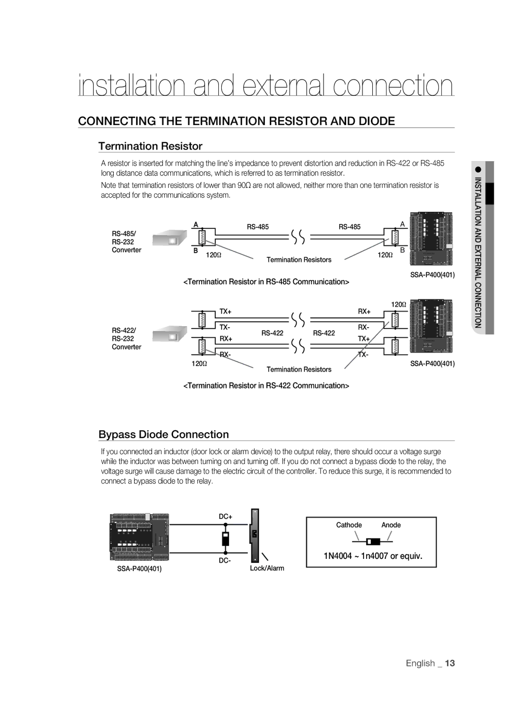
Termination Resistor
A resistor is inserted for matching the line’s impedance to prevent distortion and reduction in
Note that termination resistors of lower than 90 accepted for the communications system.
" |
| A | |||
|
|
|
|
| |
|
|
|
|
| |
Converter | # | 120Ω | Termination Resistors | 120Ω | B |
|
|
|
|
| |
|
|
|
|
|
<Termination Resistor in RS-485 Communication>
120Ω
TX+ | RX+ |
TX- | RX- | |
RX+ | TX+ | |
Converter | RX- | TX- |
| ||
| 120Ω | |
| Termination Resistors | |
<Termination Resistor in RS-422 Communication>
INSTALLATION AND EXTERNAL CONNECTION
Bypass Diode Connection
If you connected an inductor (door lock or alarm device) to the output relay, there should occur a voltage surge while the inductor was between turning on and turning off. If you do not connect a bypass diode to the relay, the voltage surge will cause damage to the electric circuit of the controller. To reduce this surge, it is recommended to connect a bypass diode to the relay.
| DC+ |
| DC- |
Lock/Alarm |
Cathode Anode
1N4004 ~ 1n4007 or equiv.
English _ 13