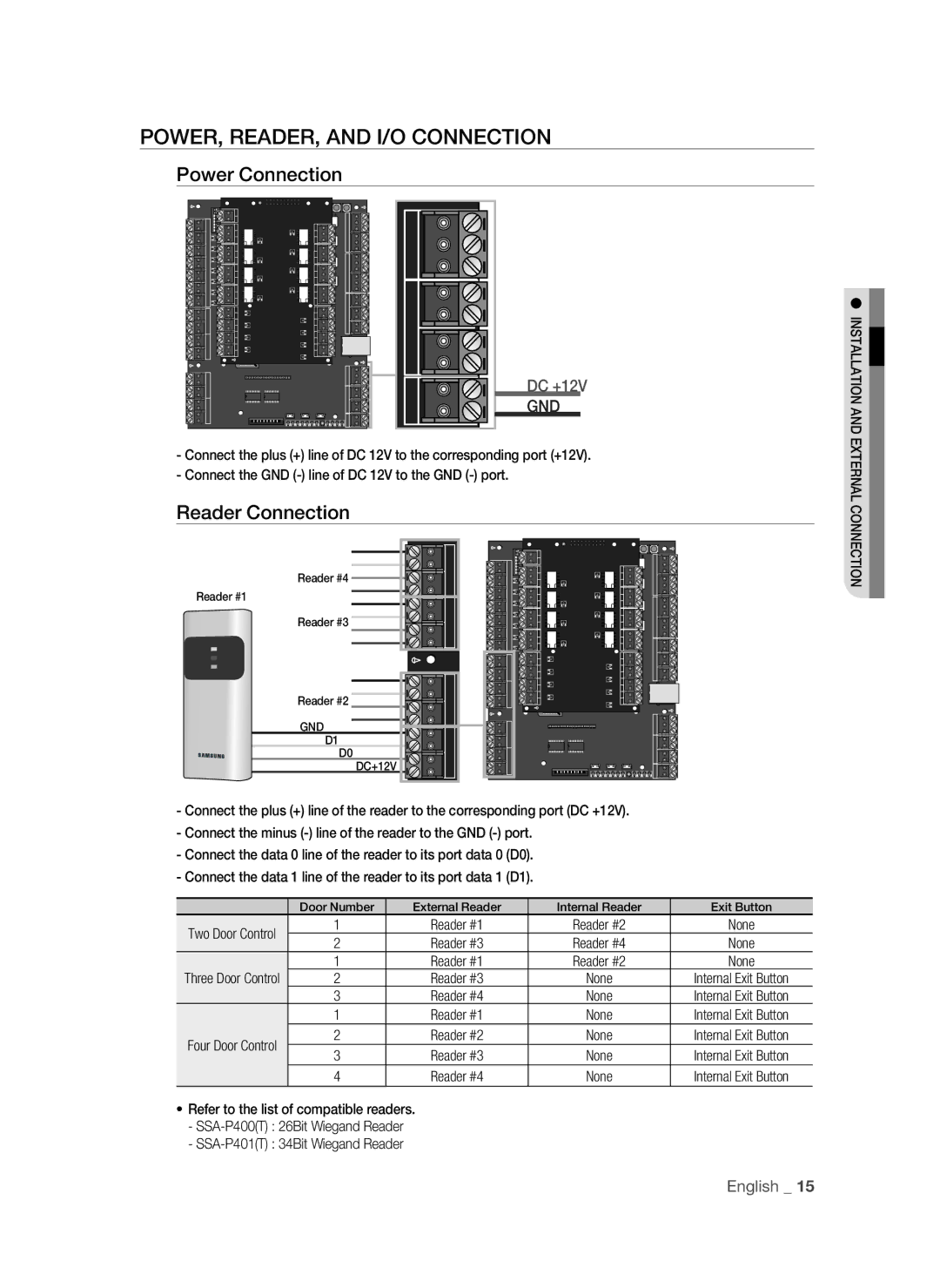
POWER, READER, AND I/O CONNECTION
Power Connection
DC +12V
GND
-Connect the plus (+) line of DC 12V to the corresponding port (+12V).
-Connect the GND
Reader Connection
Reader #4
Reader #1
Reader #3
Reader #2
GND
D1
D0
DC+12V
-Connect the plus (+) line of the reader to the corresponding port (DC +12V).
-Connect the minus
-Connect the data 0 line of the reader to its port data 0 (D0).
-Connect the data 1 line of the reader to its port data 1 (D1).
| Door Number | External Reader | Internal Reader | Exit Button | |
Two Door Control | 1 | Reader #1 | Reader #2 | None | |
2 | Reader #3 | Reader #4 | None | ||
| |||||
| 1 | Reader #1 | Reader #2 | None | |
Three Door Control | 2 | Reader #3 | None | Internal Exit Button | |
| 3 | Reader #4 | None | Internal Exit Button | |
| 1 | Reader #1 | None | Internal Exit Button | |
Four Door Control | 2 | Reader #2 | None | Internal Exit Button | |
3 | Reader #3 | None | Internal Exit Button | ||
| |||||
| 4 | Reader #4 | None | Internal Exit Button |
•Refer to the list of compatible readers.
-
-
INSTALLATION AND EXTERNAL CONNECTION
English _ 15
