Identification of Controls (continued)
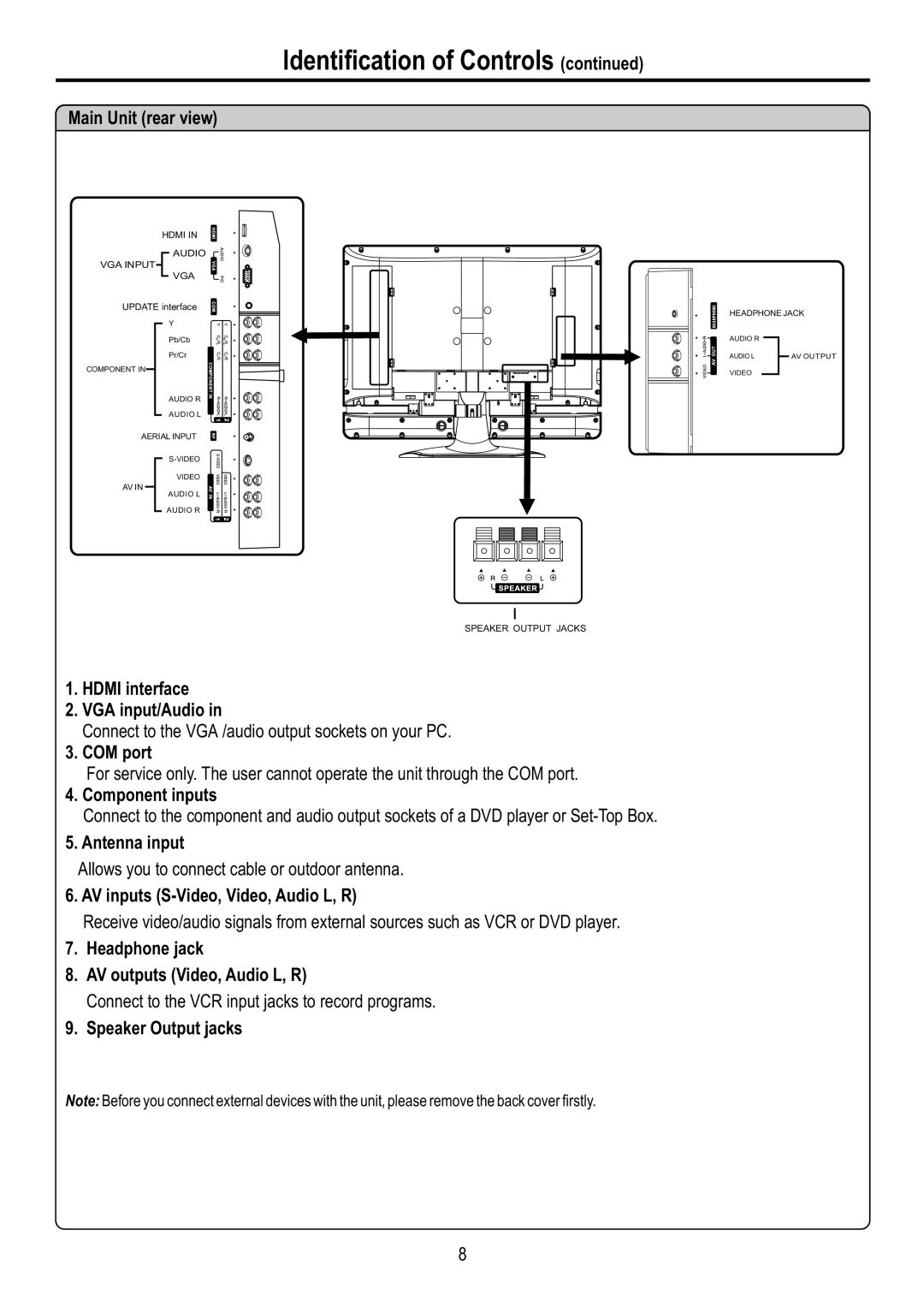
Main Unit (rear view)
HDMI IN
AUDIO
VGA INPUT
VGA
UPDATE interface
Y
Pb/Cb
Pr/Cr
COMPONENT IN
AUDIO R
AUDIO L
AERIAL INPUT
VIDEO
AV IN
AUDIO L
AUDIO R
SPEAKER OUTPUT JACKS
1.HDMI interface
2.VGA input/Audio in
Connect to the VGA /audio output sockets on your PC.
3.COM port
For service only. The user cannot operate the unit through the COM port.
4.Component inputs
Connect to the component and audio output sockets of a DVD player or
5.Antenna input
Allows you to connect cable or outdoor antenna.
6.AV inputs (S-Video, Video, Audio L, R)
Receive video/audio signals from external sources such as VCR or DVD player.
7.Headphone jack
8.AV outputs (Video, Audio L, R)
Connect to the VCR input jacks to record programs.
9.Speaker Output jacks
Note: Before you connect external devices with the unit, please remove the back cover firstly.
HEADPHONE JACK
AUDIO R
AUDIO L |
| AV OUTPUT |
VIDEO
8
