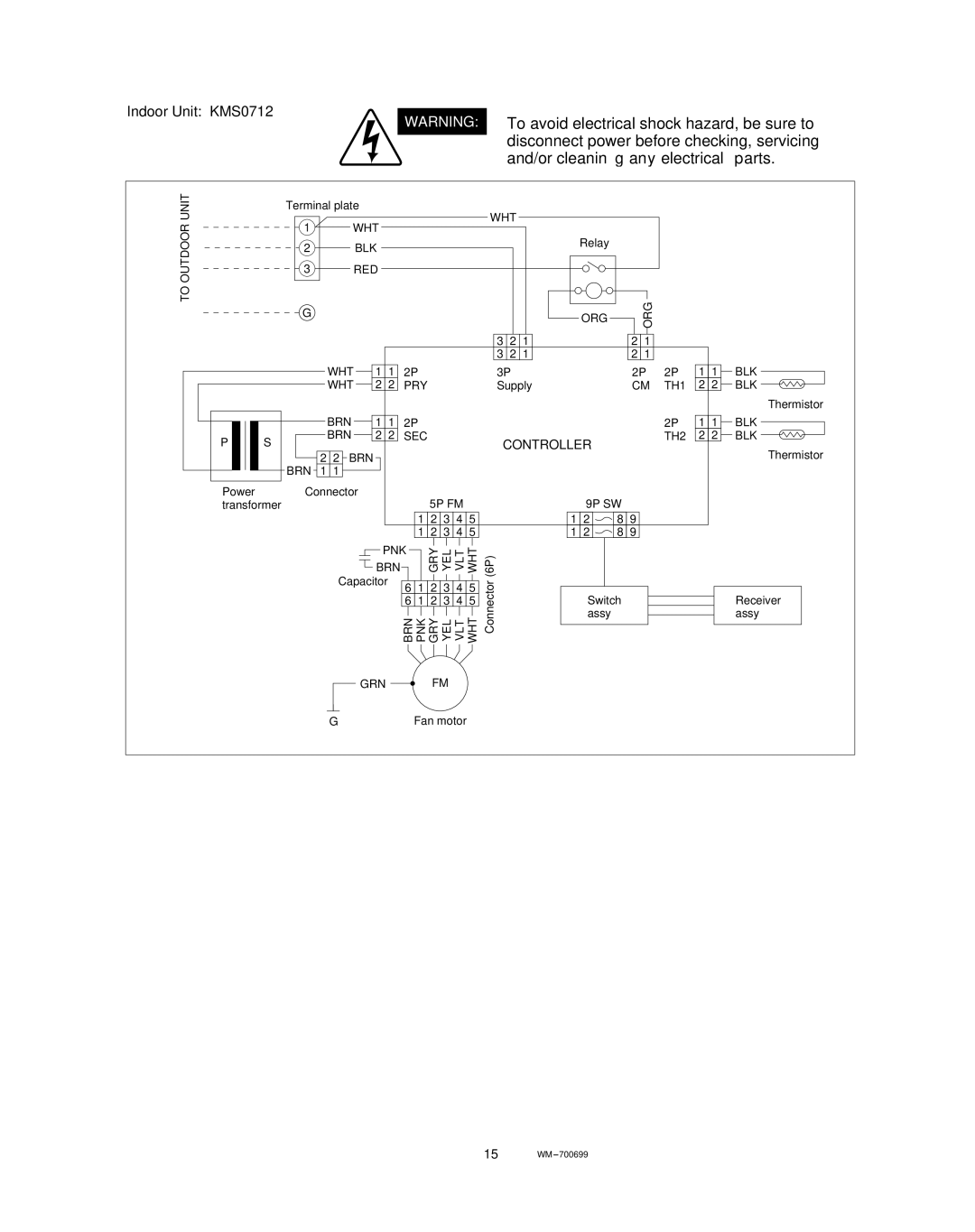
Indoor Unit: KMS0712
WARNING: To avoid electrical shock hazard, be sure to disconnect power before checking, servicing and/or cleaning any electrical parts.
TO OUTDOOR UNIT
| Terminal plate |
| ||
| 1 | WHT |
| |
| 2 |
| BLK |
|
| 3 |
| RED |
|
| G |
|
|
|
|
| WHT | 1 1 | 2P |
|
| WHT | 2 2 | PRY |
|
| BRN | 1 1 | 2P |
P | S | BRN | 2 2 | SEC |
|
|
| ||
|
| 2 2 BRN |
| |
| BRN | 1 1 |
|
|
Power | Connector | 5P FM | ||
transformer |
|
| ||
1 | 2 | 3 | 4 | 5 |
1 | 2 | 3 | 4 | 5 |
PNK |
| GRY YEL VLT WHT | ||||
BRN |
|
| ||||
Capacitor | 6 | 1 | 2 | 3 | 4 | 5 |
| ||||||
| 6 | 1 | 2 | 3 | 4 | 5 |
WHT
VLT
YEL
GRY
PNK
BRN
GRN | FM |
GFan motor
WHT
Relay |
|
ORG | ORG |
|
3 | 2 | 1 | 2 | 1 |
3 | 2 | 1 | 2 | 1 |
| 3P | 2P | 2P | 1 | 1 | BLK |
| Supply | CM | TH1 | 2 | 2 | BLK |
|
|
|
|
|
| Thermistor |
|
|
| 2P | 1 | 1 | BLK |
| CONTROLLER |
| TH2 | 2 | 2 | BLK |
|
|
|
|
| Thermistor | |
|
|
|
|
|
| |
| 9P SW |
|
|
|
| |
| 1 2 | 8 9 |
|
|
|
|
| 1 2 | 8 9 |
|
|
|
|
(6P) |
|
|
|
|
|
|
Connector | Switch |
|
|
| Receiver | |
|
|
|
| |||
| assy |
|
|
|
| assy |
15WM – 700699