4
MOUNT THE LENS
1.Remove protective caps (front and back) on the optional lens.
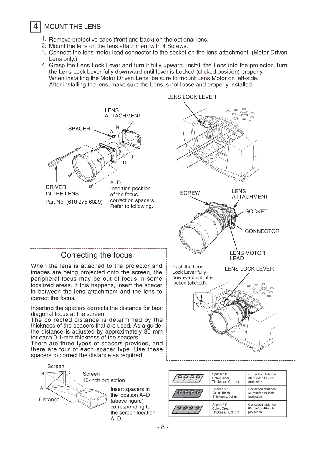
2.Mount the lens on the lens attachment with 4 Screws.
3.Connect the lens motor lead connector to the socket on the lens attachment. (Motor Driven Lens only.)
4.Grasp the Lens Lock Lever and turn it fully upward. Install the Lens into the projector. Turn the Lens Lock Lever fully downward until lever is Locked (clicked position) properly.
When installing the Motor Driven Lens, be sure to mount Lens Motor on
|
| LENS LOCK LEVER |
| LENS |
|
| ATTACHMENT |
|
SPACER | B |
|
| A |
|
| C |
|
| D |
|
DRIVER | A~D |
|
Insertion position | SCREW | |
IN THE LENS | of the focus | |
Part No. (610 275 6029) | correction spacers. |
|
Refer to following. |
| |
|
|
LENS ATTACHMENT
SOCKET
CONNECTOR
Correcting the focus
When the lens is attached to the projector and images are being projected onto the screen, the peripheral focus may be out of focus in some localized areas. If this happens, insert the spacer in between the lens attachment and the lens to correct the focus.
Inserting the spacers corrects the distance for best diagonal focus at the screen.
The corrected distance is determined by the thickness of the spacers that are used. As a guide, the distance is adjusted by approximately 30 mm for each
There are three types of spacers provided, and there are four of each spacer type. Use these spacers to correct the distance as required.
Push the Lens Lock Lever fully downward until it is locked (clicked).
LENS MOTOR
LEAD
LENS LOCK LEVER
Screen |
|
|
B | D | Screen |
|
| |
A | C | Insert spacers in |
Distance |
| the location A~D |
| (above figure) | |
|
| corresponding to |
|
| the screen location |
|
| A~D. |
| Spacer "1" | Correction distance |
| Color; Clear | 30 mm/for |
| Thickness; 0.1 mm | projection |
|
|
|
| Spacer "2" | Correction distance |
| Color; Black | 55 mm/for |
| Thickness; 0.2 mm | projection |
|
|
|
| Spacer "1" | Correction distance |
| Color; Cream | 80 mm/for |
| Thickness; 0.3 mm | projection |
|
|
|
- 8 -
