2. HOW TO INSTALL THE UNIT
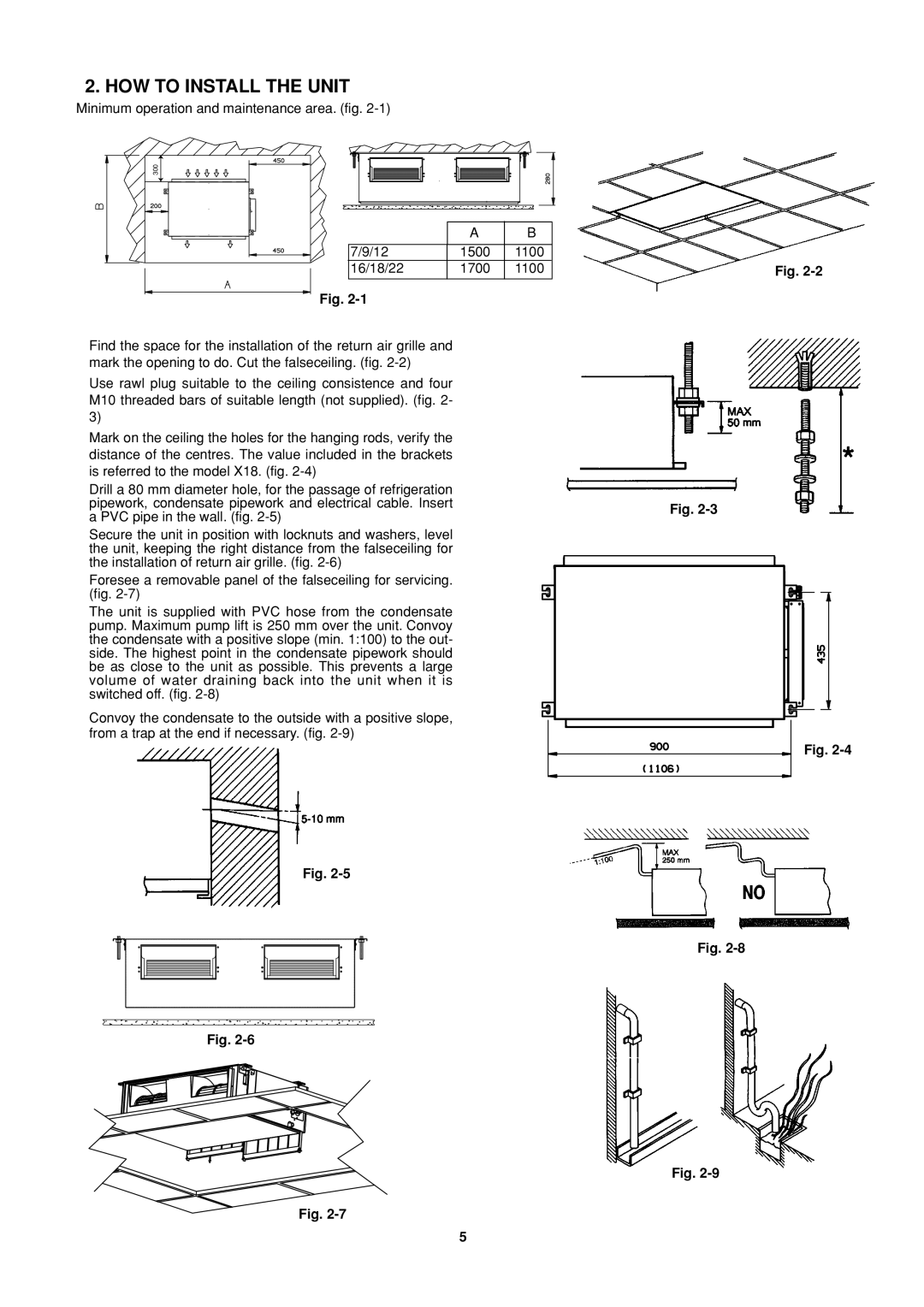
Minimum operation and maintenance area. (fig.
300
| A | B |
|
|
|
7/9/12 | 1500 | 1100 |
16/18/22 | 1700 | 1100 |
|
|
|
Fig. 2-1
Find the space for the installation of the return air grille and mark the opening to do. Cut the falseceiling. (fig.
Use rawl plug suitable to the ceiling consistence and four M10 threaded bars of suitable length (not supplied). (fig. 2- 3)
Mark on the ceiling the holes for the hanging rods, verify the distance of the centres. The value included in the brackets is referred to the model X18. (fig.
Drill a 80 mm diameter hole, for the passage of refrigeration pipework, condensate pipework and electrical cable. Insert a PVC pipe in the wall. (fig.
Secure the unit in position with locknuts and washers, level the unit, keeping the right distance from the falseceiling for the installation of return air grille. (fig.
Foresee a removable panel of the falseceiling for servicing. (fig.
The unit is supplied with PVC hose from the condensate pump. Maximum pump lift is 250 mm over the unit. Convoy the condensate with a positive slope (min. 1:100) to the out- side. The highest point in the condensate pipework should be as close to the unit as possible. This prevents a large volume of water draining back into the unit when it is switched off. (fig.
Convoy the condensate to the outside with a positive slope, from a trap at the end if necessary. (fig.
Fig. 2-5
Fig.
Fig.
Fig. 2-2
Fig.
Fig.
Fig.
Fig.
5