Scag Power Equipment STC48V-26BS, STC52V-23BV, STC61V-23BV manual Safety Interlock System

Models: STC48V-26BS, STC52V-23BV, STC61V-23BV STC61V-23BV, STC48V-26BS, STC52V-23BV, STC52V-25CV, STC52-25CV-FR, STC61V-25CV, STC61-25CV-FR

1 110
Download 110 pages 24.71 Kb
Page 17
Image 17

Section 4

5.Hourmeter (Figure 4-1). Indicates the number of hours the engine has been operated. It operates whenever the ignition key switch is in the ON position. Has preset maintenance reminders for engine and hydraulic system oil changes. Will start flashing scheduled maintenance 2 hours before preset time and continue flashing until 2 hours after. Automatically resets.

6.Fuse Holders (Figure 4-1). Two 20-amp fuses protect the mower’s electrical system. To replace fuses, pull fuse out of the socket and install a new fuse.

7.Left Steering Control (Figure 4-1). Used to control the mower's left wheel when traveling forward or reverse.

8.Right Steering Control (Figure 4-1). Used to control the mower's right wheel when traveling forward or reverse.

9.Parking Brake Control (Figure 4-1). Used to engage and disengage the parking brakes. Pull the lever back to engage the parking brakes. Push the lever forward to disengage the parking brakes.

10.Fuel Switching Valve (Figure 4-1). Located on the left side of the machine. Used to shut off fuel supply to the engine and change fuel supply between the fuel tanks. Rotate the valve counter clockwise to supply fuel from the tank on the left side only. Rotate the valve clockwise to supply fuel from the tank on the right side only.

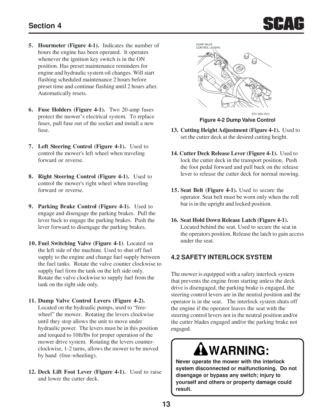
11.Dump Valve Control Levers (Figure 4-2). Located on the hydraulic pumps, used to “free- wheel” the mower. Rotating the levers clockwise until they stop allows the unit to move under hydraulic power. The levers must be in this position and torqued to 10ft/lbs for proper operation of the mower drive system. Rotating the levers counter- clockwise, 1-2 turns, allows the mower to be moved by hand (free-wheeling).

12.Deck Lift Foot Lever (Figure 4-1). Used to raise and lower the cutter deck.

DUMP VALVE

CONTROL LEVERS

STC 2001 DVC

Figure 4-2 Dump Valve Control

13.Cutting Height Adjustment (Figure 4-1). Used to set the cutter deck at the desired cutting height.

14.Cutter Deck Release Lever (Figure 4-1).Used to lock the cutter deck in the transport position. Push the foot pedal forward and pull back on the release lever to release the cutter deck for normal mowing.

15.Seat Belt (Figure 4-1). Used to secure the operator. Seat belt must be worn only when the roll bar is in the upright and locked position.

16.Seat Hold Down Release Latch (Figure 4-1). Located behind the seat. Used to secure the seat in the operators position. Release the latch to gain access under the seat.

4.2 SAFETY INTERLOCK SYSTEM

The mower is equipped with a safety interlock system that prevents the engine from starting unless the deck drive is disengaged, the parking brake is engaged, the steering control levers are in the neutral position and the operator is in the seat. The interlock system shuts off the engine if the operator leaves the seat with the steering control levers not in the neutral position and/or the cutter blades engaged and/or the parking brake not engaged.

WARNING:

Never operate the mower with the interlock system disconnected or malfunctioning. Do not disengage or bypass any switch; injury to yourself and others or property damage could result.

13

Page 17
Image 17
Scag Power Equipment STC48V-26BS, STC52V-23BV, STC61V-23BV manual Safety Interlock System, Dump Valve Control