Section 6
A.3" Position - baffle is installed using the top set of holes on the front baffle welded inside the cutter deck. (See Figure 6.9). In this position the Velocity- Plus cutter deck will deliver the best
B.
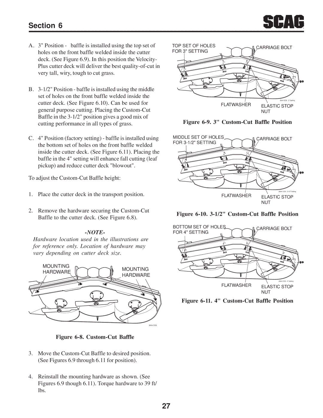
C.4" Position (factory setting) - baffle is installed using the bottom set of holes on the front baffle welded inside the cutter deck. (See Figure 6.11). Placing the baffle in the 4" setting will enhance fall cutting (leaf pickup) and reduce cutter deck "blowout".
To adjust the
1.Place the cutter deck in the transport position.
2.Remove the hardware securing the
Hardware location used in the illustrations are for reference only. Location of hardware may vary depending on cutter deck size.
MOUNTING | MOUNTING | |
HARDWARE | ||
HARDWARE | ||
|
2004 CCB
Figure 6-8. Custom-Cut Baffle
TOP SET OF HOLES | CARRIAGE BOLT | |
FOR 3" SETTING | ||
|
|
| 2004 CCB - 3" Setting | |
FLATWASHER | ELASTIC STOP | ||
|
| ||
|
| NUT | |
Figure | |||
|
|
| |
MIDDLE SET OF HOLES |
|
|
|
CARRIAGE BOLT |
| ||
FOR |
|
| |
|
|
| |
|
| 2004 CCB - | |
FLATWASHER | ELASTIC STOP | ||
|
| ||
|
| NUT | |
Figure | |||
|
|
| |
BOTTOM SET OF HOLES |
|
|
|
CARRIAGE BOLT |
| ||
FOR 4" SETTING |
|
| |
|
|
| |
| 2004 CCB - 4" Setting |
FLATWASHER | ELASTIC STOP |
| |
| NUT |
Figure 6-11. 4" Custom-Cut Baffle Position
3.Move the
4.Reinstall the mounting hardware as shown. (See Figures 6.9 though 6.11). Torque hardware to 39 ft/ lbs.
27