DeviceNet Communication Adapter
1.4Connecting to the Network
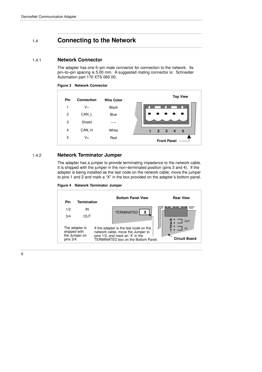
1.4.1Network Connector
The adapter has one
Figure 3 Network Connector
Pin | Connection | Wire Color |
|
|
|
|
|
|
|
|
|
| Top View |
| ||||||
|
|
|
|
|
|
|
|
|
|
|
|
|
|
|
|
|
| |||
1 | V– | Black |
|
|
|
|
|
|
|
|
|
|
|
|
|
|
|
|
|
|
|
|
|
|
|
|
|
|
|
|
|
|
|
|
|
|
|
| |||
|
|
|
|
|
|
|
|
|
|
|
|
|
|
|
|
|
| |||
2 | CAN_L | Blue |
|
|
|
|
|
|
|
|
|
|
|
|
|
|
|
|
|
|
|
|
|
|
|
|
|
|
|
|
|
|
|
|
|
|
|
| |||
|
|
|
|
|
|
|
|
|
|
|
|
|
|
|
|
|
| |||
3 | Shield | – – |
|
|
|
|
|
|
|
|
|
|
|
|
|
|
|
|
|
|
4 | CAN_H |
|
|
|
|
|
|
|
|
|
|
|
|
|
|
|
|
|
|
|
White | 1 2 3 4 5 |
| ||||||||||||||||||
5 | V+ | Red |
|
|
|
|
| Front Panel |
|
|
|
| ||||||||
|
|
|
|
|
|
|
|
| ||||||||||||
|
|
|
|
|
|
|
|
|
| |||||||||||
|
|
|
|
|
|
|
|
|
| |||||||||||
|
|
|
|
|
|
|
|
|
|
|
|
|
|
|
|
|
|
|
|
|
1.4.2Network Terminator Jumper
The adapter has a jumper to provide terminating impedance to the network cable. It is shipped with the jumper in the
Figure 4 Network Terminator Jumper
Bottom Panel View | Rear View |
Pin Termination
1/2 | IN |
|
|
|
TERMINATED | X |
| ||
3/4 | OUT |
| ||
|
|
| ||
The adapter is | If the adapter is the last node on the | |||
shipped with | network cable, move the Jumper to | |||
the Jumper on | pins 1/2, and mark an ’X’ in the | |||
pins 3/4. |
| TERMINATED box on the Bottom Panel. | ||
OUT |
IN |
Circuit Board |
6