Cheetah 15K.4 FC
ST3146954FC ST373554FC ST336854FC
Page
Cheetah 15K.4 FC
March
Revision status summary sheet
Rev. A
07/15/05
Rev. B Draft
Page
Contents
4.0 Performance characteristics
5.0 Reliability specifications
6.0 Physical/electrical specifications
9.0 Interface requirements
7.0 Defect and error management
8.0 Installation
10.0 Seagate Technology support services
Cheetah 15K.4 FC Product Manual, Rev. B
List of Figures
Page
1.0 Scope
Figure 1. Cheetah 15K.4 FC family disc drive
Cheetah 15K.4 FC Product Manual, Rev. B
2.0 Applicable standards and reference documentation
2.1 Standards
2.1.1 Electromagnetic compatibility
2.1.1.1 Electromagnetic susceptibility
2.1.2 Electromagnetic compliance
Electromagnetic compliance for the European Union
Australian C-Tick
Korean MIC
Fibre Channel Interface Manual
Specification for Acoustic Test Requirement and Procedures
2.2 Reference documents
Cheetah 15K.4 FC Product Manual, Rev. B
3.0 General description
3.1 Standard features
3.2 Media description
3.3 Performance
3.4 Reliability
3.5 Formatted capacities
3.5.1 Programmable drive capacity
3.8 User-installed accessories
3.6 Factory-installed accessories
3.7 Factory-installed options
4.0 Performance characteristics
4.1 Internal drive characteristics
4.2 Seek performance characteristics
4.2.1 Access time
4.2.2 Format command execution time minutes
General performance characteristics
4.3 Start/stop time
4.4 Prefetch/multi-segmented cache control
4.5 Cache operation
4.5.1 Caching write data
4.5.2 Prefetch operation
Cheetah 15K.4 FC Product Manual, Rev. B
Cheetah 15K.4 FC Product Manual, Rev. B
5.0 Reliability specifications
5.1 Error rates
5.1.1 Recoverable Errors
5.1.2 Unrecoverable Errors
5.2 Reliability and service
5.1.3 Seek errors
5.1.4 Interface errors
5.2.2 Preventive maintenance
Controlling S.M.A.R.T
5.2.3 Hot plugging the drive
5.2.4 S.M.A.R.T
Fully-enabled delay
Performance impact
Maximum processing delay
On-line only delay
Parameter Code
Description
5.2.6 Drive Self Test DST
5.2.6.1 DST failure definition
5.2.6.2.1 State of the drive prior to testing
5.2.6.2 Implementation
5.2.6.2.2 Invoking DST
5.2.6.2.3 Short and extended tests
5.2.7 Product warranty
5.2.6.2.4 Log page entries
5.2.6.2.5 Abort
Shipping
Product repair and return information
6.2 DC power requirements
6.0 Physical/electrical specifications
6.1 AC power requirements
3 See +12V current profile in Figure
General DC power requirement notes
6.2.2 Power sequencing
6.2.1 Conducted noise immunity
6.2.3 Current profiles
Figure 2. Typical ST3146954FC drive, 2 Gbit, +12V current profile
Figure 3. Typical ST3146954FC drive, 2 Gbit, +5V current profile
Figure 4. Typical ST373554FC drive +12V current profile
Figure 5. Typical ST373554FC drive +5V current profile
Figure 6. Typical ST336854FC drive +12V current profile
Figure 7. Typical ST336854FC drive +5V current profile
6.3 Power dissipation
ST3146954FC
ST373554FC
Power watts
ST336854FC
6.4.2 Relative humidity
6.4 Environmental limits
6.4.1 Temperature a. Operating
6.4.4.1 Shock
6.4.3 Effective altitude sea level a. Operating
6.4.4 Shock and vibration
Packaged/product weight
Package size
Drop height
Figure 12. Recommended mounting
6.4.5 Air cleanliness
6.4.4.2 Vibration a. Operating-normal
6.4.6 Acoustics
6.4.7 Electromagnetic susceptibility
6.5 Mechanical specifications
Figure 13. Mounting configuration dimensions
7.2 Drive error recovery procedures
7.0 Defect and error management
7.1 Drive internal defects/errors
Cheetah 15K.4 FC Product Manual, Rev. B
7.3 FC-AL system errors
7.4 Background Media Scan
7.4.1 Media Pre-Scan
8.0 Installation
8.1 Drive ID/option selection
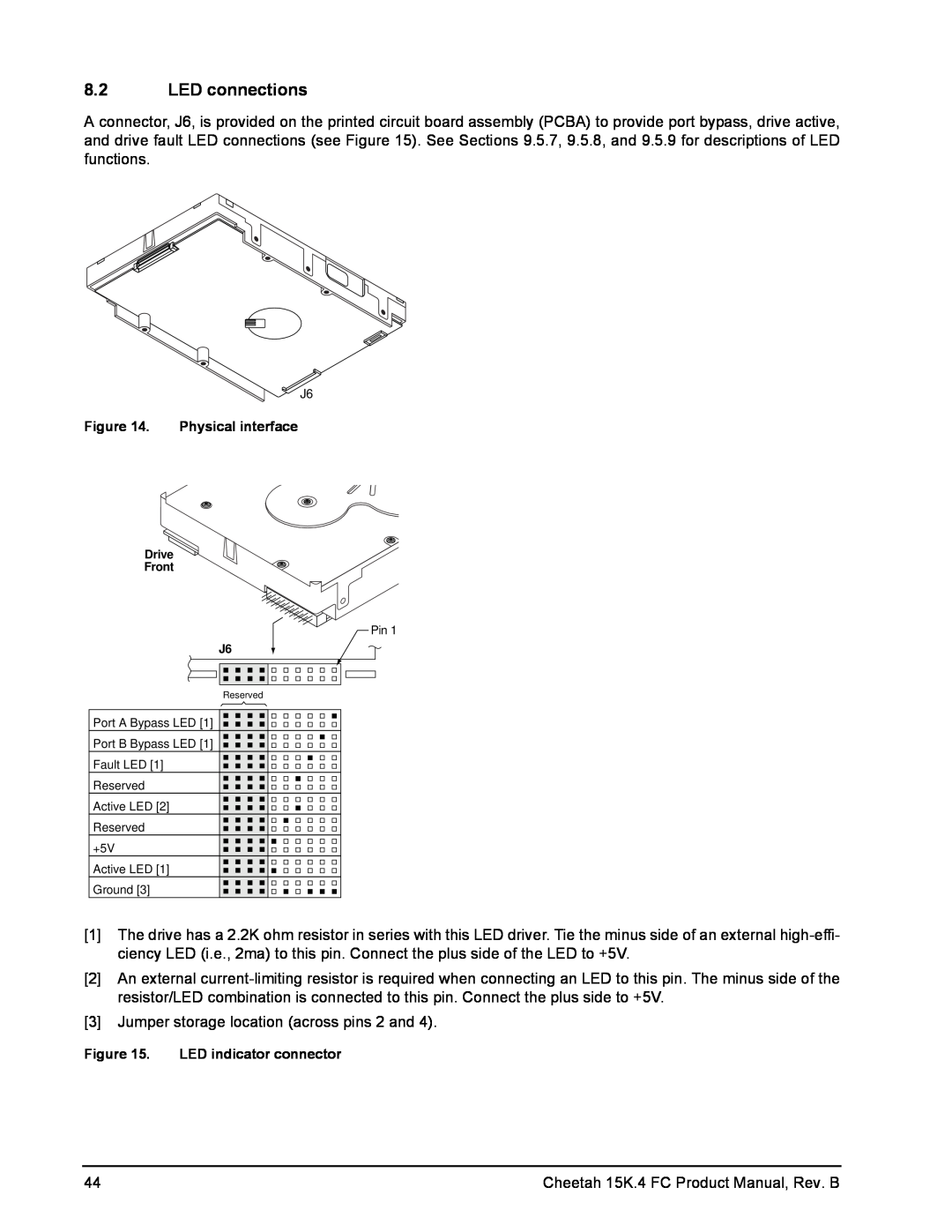
Figure 14. Physical interface
8.2 LED connections
Figure 15. LED indicator connector
8.4 Cooling
8.2.1 J6 connector requirements
8.3 Drive orientation
K x X = F 15lb = 67N
8.5 Drive mounting
8.6 Grounding
9.0 Interface requirements
9.1 FC-AL features
9.1.1 Fibre Channel link service frames
9.1.2 Fibre Channel task management functions
9.1.3 Fibre Channel task management responses
Fibre Channel SCSI FCP task management functions
Task name
Bytes
9.1.4 Fibre Channel port login
NPort login PLOGI payload
9.1.5 Fibre Channel port login accept
9.1.6 Fibre Channel Process Login
NPort Login Accept ACC payload
Process Login PLRI payload
9.1.7 Fibre Channel Process Login Accept
9.1.8 Fibre Channel fabric login
Process Login Accept ACC payload
Fabric Login FLOGI payload
9.1.9 Fibre Channel fabric accept login
Fabric Login Accept ACC payload
9.2 Dual port support
9.1.10 Fibre Channel Arbitrated Loop options
9.3 SCSI commands supported
Table 16 Supported commands
Command code
Command name
Table 16 Supported commands continued
Table 16 Supported commands continued
3 Reference Mode Sense command 1Ah for mode pages supported
9.3.1 Inquiry data
9.3.2 Mode Sense data
CHG = Changeable bits indicates if default value is changeable
3. Current values
4. Changeable values
Definitions SAV = Current saved value
MODE SENSE 10 BYTE HEADER DATA
Cheetah 15K.4 FC Product Manual, Rev. B
Cheetah 15K.4 FC Product Manual, Rev. B
9.4 Miscellaneous operating features and conditions
Miscellaneous features
Feature or condition
Miscellaneous status
9.5.1.1 Physical description
9.5.1 Physical characteristics
9.5 FC-AL physical interface
9.5.2 Connector requirements
Features
FC-AL SCA device connector dimensions
Figure 20. J6 connector dimensions
9.5.3 Electrical description
9.5.4 Pin descriptions
9.5.6 Power
9.5.7 Fault LED Out
9.5.5 FC-AL transmitters and receivers
Figure 21. FC-AL transmitters and receivers
9.5.9 Enable port bypass signals
9.5.8 Active LED Out
9.5.10 Motor start controls
Normal command activity
9.5.11.1 Parallel Enclosure Services Interface ESI
9.5.11 SEL6 through SEL0 ID lines
Setting
Arbitrated loop physical address ALPA values
ALPA
SEL ID
9.6 Signal characteristics
TTL input characteristics
9.5.12 Device control codes
9.6.1
9.6.2 LED driver signals
9.6.3 FC Differential output
9.6.4 FC Differential input
Bit Time Vout mv XMIT Eye
Receive eye diagram
Eye diagram data values
Vin mv
941 ps 659 ps 376 ps
Cheetah 15K.4 FC Product Manual, Rev. B
10.0 Seagate Technology support services
Online services
Seagate Service Centers
Internet
Customer Service Operations
USA/Canada/Latin America support services Seagate Service Centers
Warranty Service
Data Recovery Services
European support services
Africa/Middle East support services
FAX services-All Europe toll call
Warranty Service
Asia/Pacific support services
Index
Numerics
Download microcode with offsets and save mode 7
front panel 38 FS 49, 50, 52 function
pin descriptions 66 PN 49
mounting 46 holes 46 orientations
NN 49
Self-Monitoring Analysis and Reporting Technology 9
UI 50, 51 unformatted
SMP = 1 in Mode Select command 63 SO 49
LED driver 72 single-unit shipping pack kit 10 SMART 9
Page
Seagate Technology LLC