Cheetah 15K.5 FC
ST3300655FC ST3146855FC ST373455FC
Page
Contents
Interface requirements
Defect and error management
Installation
Seagate Technology support services
Cheetah 15K.5 FC Product Manual, Rev. F
List of Figures
Page
Scope
Cheetah 15K.5 FC Product Manual, Rev. F
Applicable standards and reference documentation
Standards
Electromagnetic compatibility
Electromagnetic susceptibility
European Union Restriction of Hazardous Substances RoHS
Reference documents
Ncits TR-20
Cheetah 15K.5 FC Product Manual, Rev. F
General description
Standard features
Media description
Performance
Reliability
Formatted capacities
Programmable drive capacity
User-installed accessories
Factory-installed accessories
Factory-installed options
Performance characteristics
Internal drive characteristics
Seek performance characteristics
Access time
Format command execution time minutes
General performance characteristics
Start/stop time
Prefetch/multi-segmented cache control
Cache operation
Caching write data
Prefetch operation
Reliability specifications
Error rates
Recoverable Errors
Unrecoverable Errors
Reliability and service
Seek errors
Interface errors
Preventive maintenance
4 S.M.A.R.T
Controlling S.M.A.R.T
Performance impact
Milliseconds
Reporting control
Determining rate
Predictive failures
Thermal monitor
State of the drive prior to testing
Parameter Code Description
Drive Self Test DST
DST failure definition
Invoking DST
Short and extended tests
Short test Function Code 001b
Extended test Function Code 010b
Product warranty
Abort
Shipping
Product repair and return information
Cheetah 15K.5 FC Product Manual, Rev. F
Physical/electrical specifications
AC power requirements
DC power requirements
DC power requirements for ST3300655FC model Gbit Amps
DC power requirements for ST3146855FC model Gbit Amps
DC power requirements for ST373455FC model Gbit Amps
General DC power requirement notes
Power sequencing
Conducted noise immunity
Current profiles
Typical ST3300655FC drive, 4 Gbit, +12V current profile
Typical ST3146855FC drive, 4 Gbit, +12V current profile
Typical ST373455FC drive, 4 Gbit, +12V current profile
Power dissipation
ST3300655FC
ST3146855FC CURRENT/POWER vs Throughput FC 4GB
ST3146855FC
Temperature
ST373455FC CURRENT/POWER vs Throughput FC 4GB
Environmental limits
ST373455FC
Relative humidity
Effective altitude sea level
Shock and vibration
Shock
Package size Packaged/product weight Drop height
Recommended mounting
Air cleanliness
Vibration
Acoustics
Corrosive environment
RoHS compliance statement
Mechanical specifications
Mounting configuration dimensions
Cheetah 15K.5 FC Product Manual, Rev. F
Drive error recovery procedures
Defect and error management
Drive internal defects/errors
Page
FC-AL system errors
Background Media Scan
Idle Read After Write
Media Pre-Scan
Deferred Auto-Reallocation
Installation
Drive ID/option selection
Drive orientation
Cooling
Drive mounting
Air flow
Grounding
Cheetah 15K.5 FC Product Manual, Rev. F
FC-AL features
Fibre Channel link service frames
Link services supported Type of frame
Interface requirements
FC Scsi FCP response codes Function name Response code
Fibre Channel task management functions
Fibre Channel task management responses
Fibre Channel port login
NPort login Plogi payload Bytes
Fibre Channel port login accept
Fibre Channel Process Login
NPort Login Accept ACC payload Bytes
Process Login Plri payload
Fibre Channel Process Login Accept
Fibre Channel fabric login
Process Login Accept ACC payload Bytes
Fabric Login Flogi payload Bytes
Fibre Channel fabric accept login
Fabric Login Accept ACC payload Bytes
Dual port support
Fibre Channel Arbitrated Loop options
FC-AL options supported
Option Supported
Scsi commands supported
Supported commands Command code Command name
Verify error recovery page 07h
Cheetah 15K.5 FC Product Manual, Rev. F
Temperature page 0Dh
Cheetah 15K.5 FC inquiry data Bytes Data hex
Mode Sense data
Inquiry data
Page
Mmode Sense 10 Byte Header Data
Mode Sense 10 Byte Header Data
00 ae 00 10 00 00 00 08 08 8b b9 98 00 00 02
Miscellaneous operating features and conditions
Miscellaneous features
Supported Feature or condition
Miscellaneous status
Physical description
Physical characteristics
FC-AL physical interface
Pin descriptions
Connector requirements
Electrical description
FC-AL transmitters and receivers
FC-SCA pin descriptions Pin Signal name Signal type
Pin Signal name Signal type
Power
Fault LED Out
Motor start controls
Enable port bypass signals
Active LED Out
Parallel Enclosure Services Interface ESI
11 SEL6 through SEL0 ID lines
Hex Dec
Setting
Arbitrated loop physical address Alpa values
Device control codes
Signal characteristics
TTL input characteristics
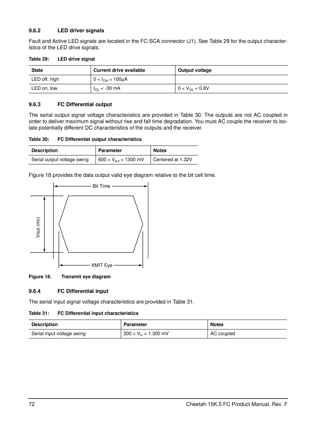
FC Differential input
LED driver signals
FC Differential output
Receive eye diagram Eye diagram data values Link rate GHz
Cheetah 15K.5 FC Product Manual, Rev. F
Seagate Technology support services
Internet
Presales Support
Technical Support
Data Recovery Services Call Center Toll-free Direct dial
Warranty Service
Data Recovery Services Authorized Service Centers
Index
Numerics
FAN
Flogi
Plogi
Page
See also cooling