6 | ST9144 Family Installation Guide, Rev. B |
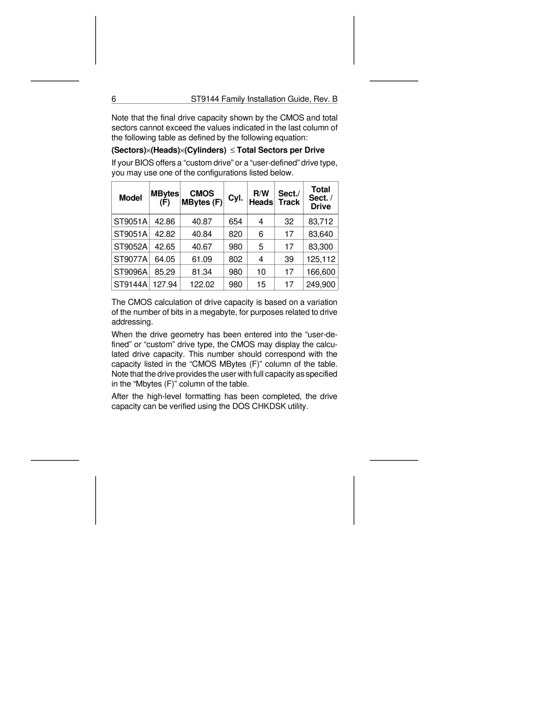
Note that the final drive capacity shown by the CMOS and total sectors cannot exceed the values indicated in the last column of the following table as defined by the following equation:
(Sectors)×(Heads)×(Cylinders) ≤ Total Sectors per Drive
If your BIOS offers a “custom drive” or a
| MBytes | CMOS |
| R/W | Sect./ | Total | |
Model | Cyl. | Sect. / | |||||
(F) | MBytes (F) | Heads | Track | ||||
|
|
|
|
|
| Drive | |
|
|
|
|
|
|
| |
ST9051A | 42.86 | 40.87 | 654 | 4 | 32 | 83,712 | |
ST9051A | 42.82 | 40.84 | 820 | 6 | 17 | 83,640 | |
ST9052A | 42.65 | 40.67 | 980 | 5 | 17 | 83,300 | |
ST9077A | 64.05 | 61.09 | 802 | 4 | 39 | 125,112 | |
ST9096A | 85.29 | 81.34 | 980 | 10 | 17 | 166,600 | |
ST9144A | 127.94 | 122.02 | 980 | 15 | 17 | 249,900 | |
|
|
|
|
|
|
|
The CMOS calculation of drive capacity is based on a variation of the number of bits in a megabyte, for purposes related to drive addressing.
When the drive geometry has been entered into the
After the