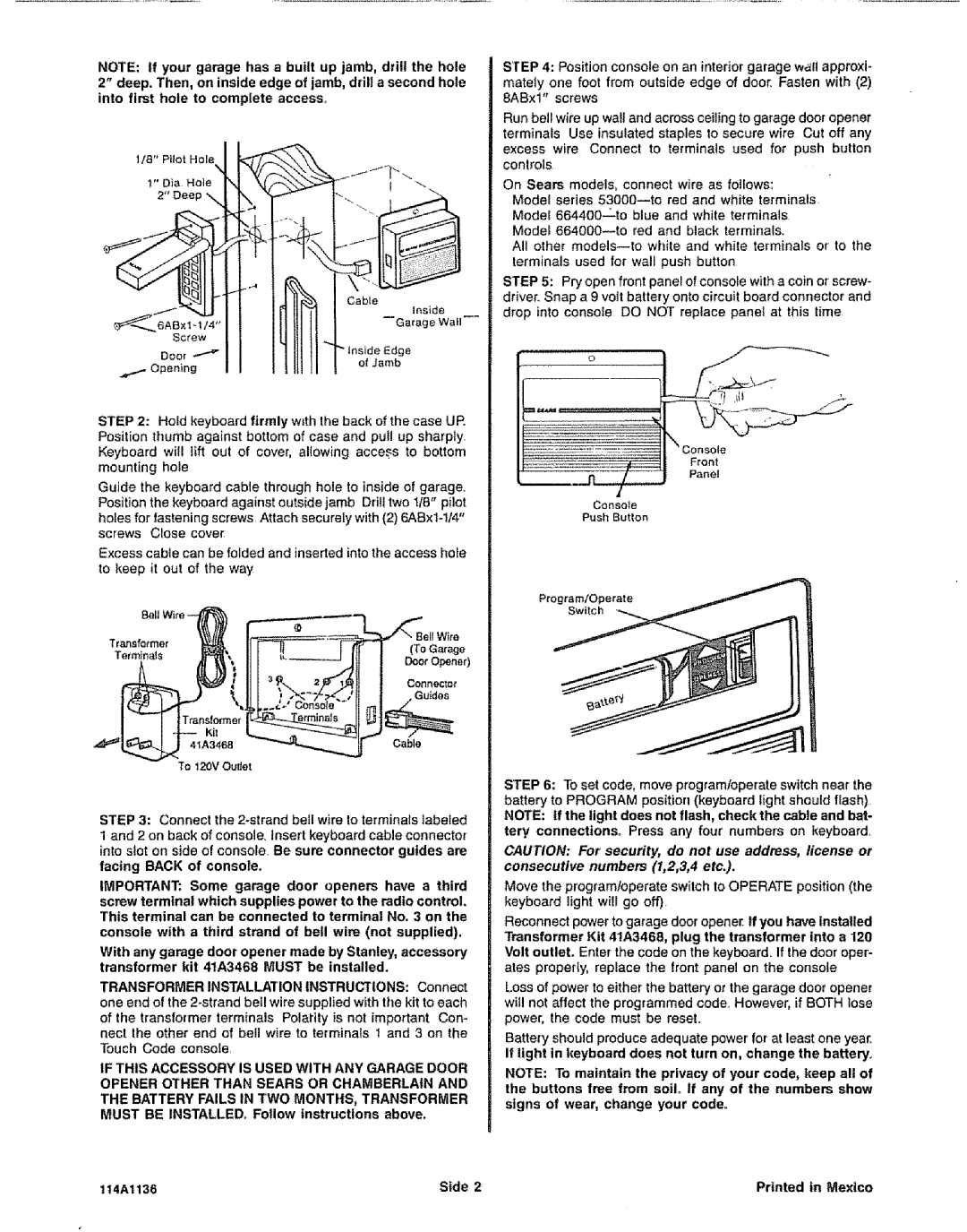
NOTE: if your garage has a built up jamb, drill the hole 2" deep. Then, on inside edge of jamb, drill a second hole into first hole to complete access_
l/8" | Pilot | Hole | I | |
|
|
| "4 |
|
1" | Dia | Hole | N | \,J,_\"_ |
Screw I I IL!III!IM
ooo, --_ I I I IIit tl rlnsi,deEdge
STEP 4: Position console on an interior garage wall approxi- mately one foot from outside edge of door. Fasten with (2) 8ABxl" screws
Run bell wire up wall and across ceiling to garage door opener terminals Use insulated staples to secure wire Cut off any excess wire Connect to terminals used for push button controls
On Sears models, connect wire as follows:
Model series
All other models_to white and white terminals or to the terminals used for wall push button
STEP 5: Pry open front panel of console with a coin or screw- driver. Snap a 9 voIt battery onto circuit board connector and drop into console DO NOT replace panel at this time
STEP 2: Hold keyboard firmly with the back of the case UP. Position thumb against bottom of case and pull up sharply Keyboard will lift out of cover, allowing access to bottom mounting hole
Guide the keyboard cable through hole to inside of garage.
Position the keyboard against outside jamb Drill two 1/8" pilot holes for fastening screws Attach securely with (2)
Excess cable can be folded and inserted into the access ho_e to keep it out of the way
| Bell Wife |
Transformer | (To Garage |
TerminaJs | Doer Opener) |
| Con ne,;,"lr_O |
| Guides |
Console
Push Button
Kit
4'_A3468Cable
To 120V Ou#et
STEP 3: Connect the
1 and 2 on back of console, insert keyboard cable connector
into slot on side of console Be sum connector guides are facing BACK of consote.
IMPORTANT; Some garage door openers have a third
screw terminal which supplies power to the radio control. This terminal can be connected to terminal No. 3 on the
console with a third strand of bell wire (not supplied).
With any garage door opener made by Stanley, accessory transformer kit 41A3468 MUST be installed.
TRANSFORMER INSTALLATION INSTRUCTIONS: Connect
one end of the
of the transformer terminals Polarity is not imporlant Con- nect the other end of bell wire to terminals 1 and 3 on the
Touch Code console.
IF THIS ACCESSORY IS USED WITH ANY GARAGE DOOR OPENER OTHER THAN SEARS OR CHAMBERLAIN AND THE BATTERY FAILS IN TWO MONTHS, TRANSFORMER
MUST BE INSTALLED° Follow instructions above.
STEP 6: To set code, move programloperate switch near the battery to PROGRAM position (keyboard light should flash) NOTE: If the light does not flash, check the cable and bat- tery connections° Press any four numbers on keyboard
CAUTION: For security, do not use address, license or consecutive numbers (1,2,3,4 etc.).
Move the programloperate switch to OPERATE position (the keyboard light will go off)
Reconnect power to garage door opener If you have installed
Transformer Kit 41A3468, plug the transformer into a 120 Volt outlet. Enter the code on the keyboard. If the door oper- ates properfy, replace the front panet on the console
Loss of power to either the battery or the garage door opener will not affect the programmed code. However, if BOTH lose power, the code must be reseL
Battery should produce adequate power for at least one year_
If light in keyboard does not turn on, change the battery.
NOTE: To maintain the privacy of your code, keep all of
the buttons free from soU° If any of the numbers show signs of wear, change your code°
114Al136 | Stde 2 | Printed In Mexico |