ASSEMBLY INSTRUCTIONS
STEP 5
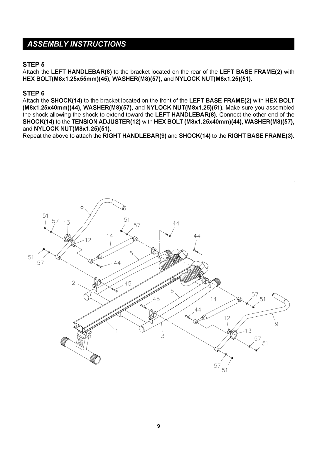
Attach the LEFT HANDLEBAR(8) to the bracket located on the rear of the LEFT BASE FRAME(2) with HEX BOLT(M8x1.25x55mm)(45), WASHER(M8)(57), and NYLOCK NUT(M8x1.25)(51).
STEP 6
Attach the SHOCK(14) to the bracket located on the front of the LEFT BASE FRAME(2) with HEX BOLT (M8x1.25x40mm)(44), WASHER(M8)(57), and NYLOCK NUT(M8x1.25)(51). Make sure you assembled the shock allowing the shock to extend toward the LEFT HANDLEBAR(8). Connect the other end of the SHOCK(14) to the TENSION ADJUSTER(12) with HEX BOLT (M8x1.25x40mm)(44), WASHER(M8)(57), and NYLOCK NUT(M8x1.25)(51).
Repeat the above to attach the RIGHT HANDLEBAR(9) and SHOCK(14) to the RIGHT BASE FRAME(3).
9