ASSEMBLY
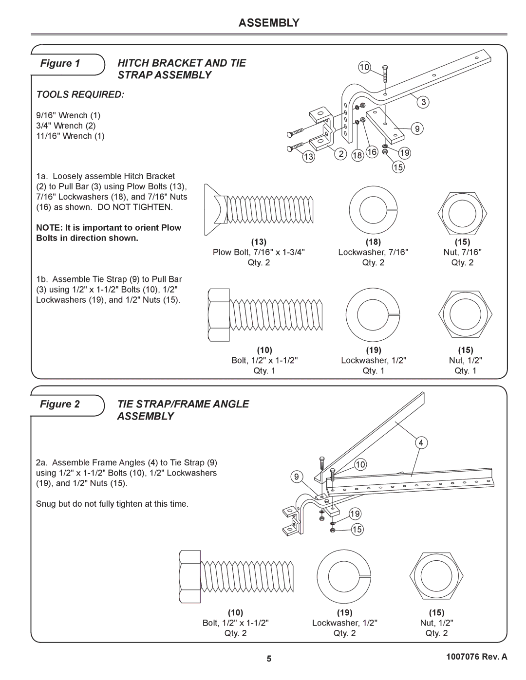
Figure 1 | HITCH BRACKET AND TIE |
| 10 |
| |
| STRAP ASSEMBLY |
|
|
|
|
TOOLS REQUIRED: |
|
|
| 3 | |
|
|
|
|
| |
9/16" Wrench (1) |
|
|
|
|
|
3/4" Wrench (2) |
|
|
|
| 9 |
11/16" Wrench (1) |
|
|
|
| |
|
|
|
|
| |
| 13 | 2 | 18 | 16 | 19 |
1a. Loosely assemble Hitch Bracket |
|
|
| 15 | |
|
|
|
| ||
(2)to Pull Bar (3) using Plow Bolts (13), 7/16" Lockwashers (18), and 7/16" Nuts
(16)as shown. DO NOT TIGHTEN.
NOTE: It is important to orient Plow |
|
|
|
Bolts in direction shown. | (13) | (18) | (15) |
| |||
| Plow Bolt, 7/16" x | Lockwasher, 7/16" | Nut, 7/16" |
| Qty. 2 | Qty. 2 | Qty. 2 |
1b. Assemble Tie Strap (9) to Pull Bar
(3)using 1/2" x
(10) | (19) | (15) |
Bolt, 1/2" x | Lockwasher, 1/2" | Nut, 1/2" |
Qty. 1 | Qty. 1 | Qty. 1 |
Figure 2 TIE STRAP/FRAME ANGLE
ASSEMBLY
2a. Assemble Frame Angles (4) to Tie Strap (9)
using 1/2" x
Snug but do not fully tighten at this time.
4 |
10
19
15
(10) | (19) | (15) |
Bolt, 1/2" x | Lockwasher, 1/2" | Nut, 1/2" |
Qty. 2 | Qty. 2 | Qty. 2 |
5 |
| 1007076 Rev. A |
