ASSEMBLY
================================================================================================
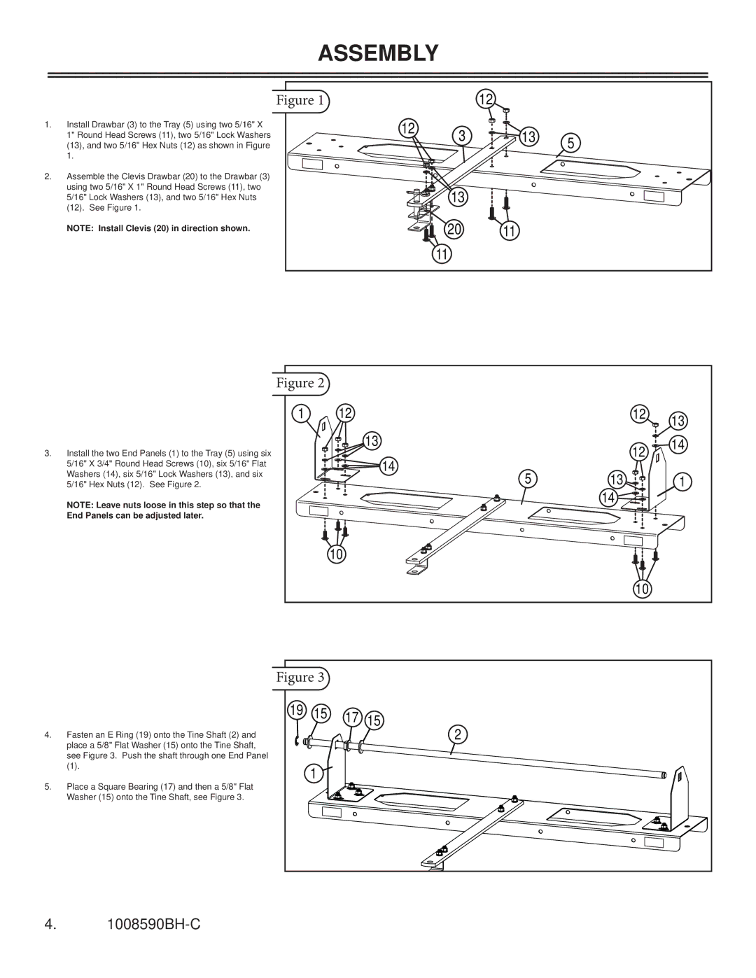
1.Install Drawbar (3) to the Tray (5) using two 5/16" X 1" Round Head Screws (11), two 5/16" Lock Washers (13), and two 5/16" Hex Nuts (12) as shown in Figure 1.
2.Assemble the Clevis Drawbar (20) to the Drawbar (3) using two 5/16" X 1" Round Head Screws (11), two 5/16" Lock Washers (13), and two 5/16" Hex Nuts (12). See Figure 1.
NOTE: Install Clevis (20) in direction shown.
Figure 1 |
| 12 |
|
12 | 3 | 13 | 5 |
| |||
|
|
| |
| 13 |
|
|
| 20 | 11 |
|
| 11 |
|
|
Figure 2
3.Install the two End Panels (1) to the Tray (5) using six 5/16" X 3/4" Round Head Screws (10), six 5/16" Flat Washers (14), six 5/16" Lock Washers (13), and six 5/16" Hex Nuts (12). See Figure 2.
NOTE: Leave nuts loose in this step so that the End Panels can be adjusted later.
1 | 12 |
| 12 | 13 |
|
|
|
| |
| 13 |
| 12 | 14 |
| 14 |
|
| |
|
|
|
| |
| 5 | 13 |
| 1 |
|
| 14 |
|
|
| 10 |
|
|
|
|
|
| 10 |
|
4.Fasten an E Ring (19) onto the Tine Shaft (2) and place a 5/8" Flat Washer (15) onto the Tine Shaft, see Figure 3. Push the shaft through one End Panel
(1).
5.Place a Square Bearing (17) and then a 5/8" Flat Washer (15) onto the Tine Shaft, see Figure 3.
Figure 3
19 | 15 | 17 | 15 |
|
|
| 2 |
| 1 |
|
|
4.