Sharp ER-A440 manual Key Top Kit, Installation procedure, Outline, ER-11KT7

Models: ER-A440

1 9
Download 9 pages 52.58 Kb
Page 7
Image 7
CHAPTER 9. KEY TOP KIT

8)Solder the Connector (2 pin)  ER-11KT7 CN8 NEJ)

to the Main PWB unit. (Location:

Solder the connector(2pin).

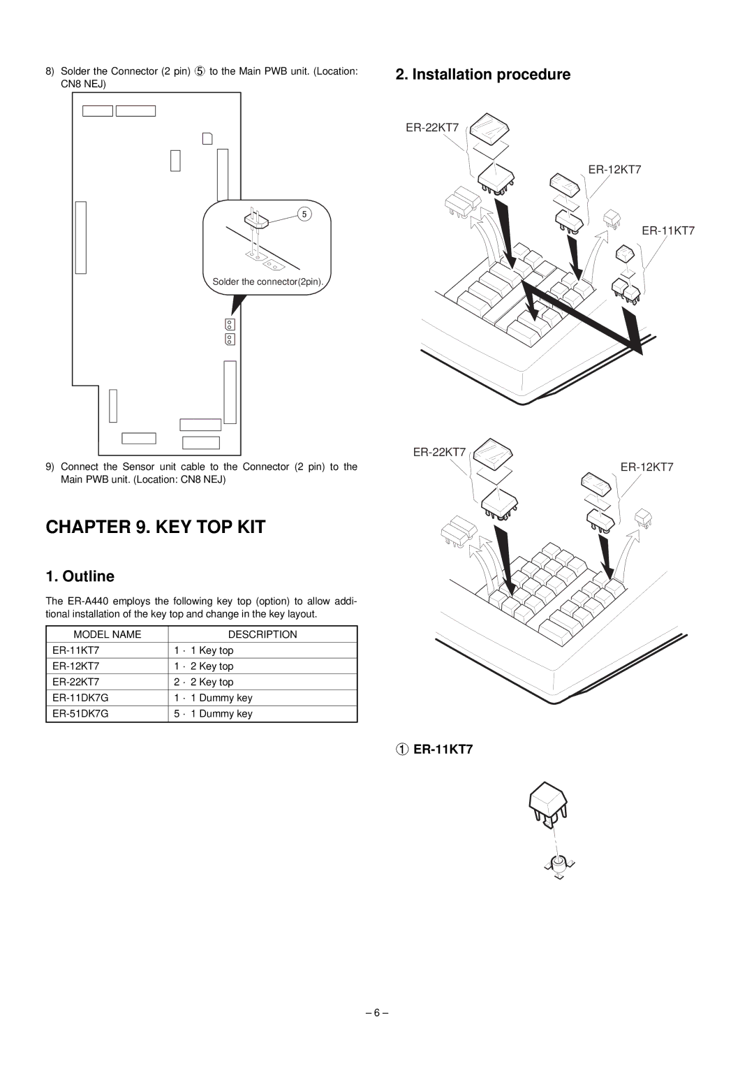
2. Installation procedure

ER-22KT7

ER-12KT7

ER-11KT7

ER-22KT7

9)Connect the Sensor unit cable to the Connector (2 pin) to the Main PWB unit. (Location: CN8 NEJ)

CHAPTER 9. KEY TOP KIT

1. Outline

The ER-A440 employs the following key top (option) to allow addi- tional installation of the key top and change in the key layout.

MODEL NAME


DESCRIPTION


ER-11KT7

1

1 Key top


ER-12KT7

1

2 Key top


ER-22KT7

2

2 Key top


ER-11DK7G

1

1 Dummy key


ER-51DK7G

5

1 Dummy key


ER-12KT7

Manual background ER-11KT7

– 6 –

Page 7
Image 7
Sharp ER-A440 manual Key Top Kit, Installation procedure, Outline, ER-11KT7