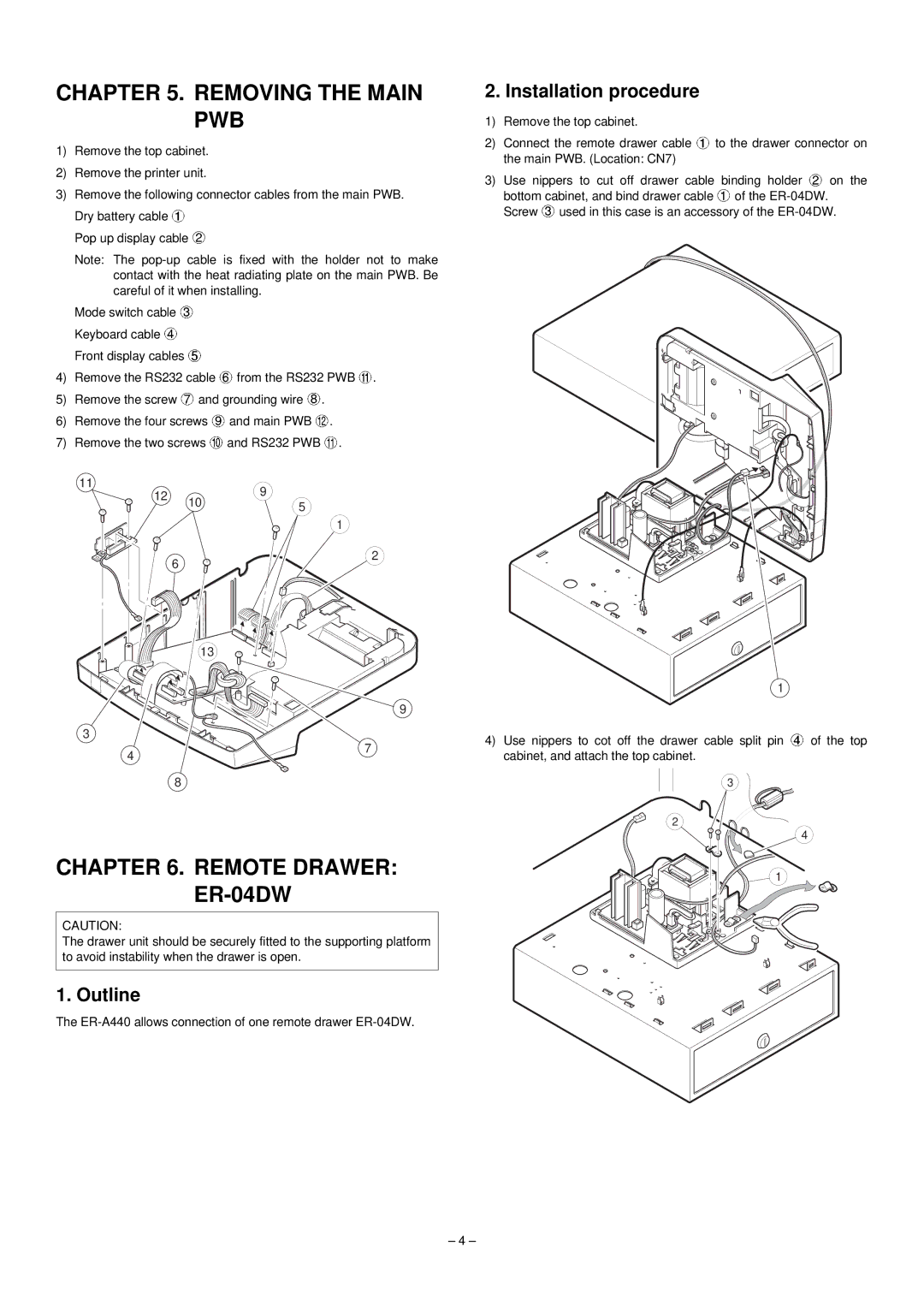
CHAPTER 5. REMOVING THE MAIN PWB
1)Remove the top cabinet.
2)Remove the printer unit.
3)Remove the following connector cables from the main PWB. Dry battery cable ![]()
Pop up display cable ![]()
Note: The
Mode switch cable ![]() Keyboard cable
Keyboard cable ![]() Front display cables
Front display cables ![]()
4)Remove the RS232 cable ![]() from the RS232 PWB
from the RS232 PWB ![]() .
.
5)Remove the screw ![]() and grounding wire
and grounding wire ![]() .
.
6)Remove the four screws ![]() and main PWB
and main PWB ![]() .
.
7)Remove the two screws ![]() and RS232 PWB
and RS232 PWB ![]() .
.
11 |
| 9 | |
12 | 10 | ||
5 | |||
| |||
|
| ||
|
| 1 | |
| 6 | 2 | |
|
|
13
2. Installation procedure
1)Remove the top cabinet.
2)Connect the remote drawer cable ![]() to the drawer connector on the main PWB. (Location: CN7)
to the drawer connector on the main PWB. (Location: CN7)
3)Use nippers to cut off drawer cable binding holder ![]() on the bottom cabinet, and bind drawer cable
on the bottom cabinet, and bind drawer cable ![]() of the
of the ![]() used in this case is an accessory of the
used in this case is an accessory of the
1
3
4
9
7
4)Use nippers to cot off the drawer cable split pin ![]() of the top cabinet, and attach the top cabinet.
of the top cabinet, and attach the top cabinet.
8
CHAPTER 6. REMOTE DRAWER: ER-04DW
CAUTION:
The drawer unit should be securely fitted to the supporting platform to avoid instability when the drawer is open.
1. Outline
The
3
2
4
![]() 1
1
– 4 –