
CR560X specifications
The Jensen CR560X is a versatile and feature-rich multimedia receiver designed to enhance your in-car audio experience. This compact unit offers a blend of modern technology and user-friendly functionality, making it a popular choice among car audio enthusiasts.One of the standout features of the Jensen CR560X is its connectivity options. It supports Bluetooth technology, allowing users to wirelessly stream music from their smartphones or other devices. This means that you can enjoy your favorite playlists, podcasts, and calls without the hassle of tangled wires. Additionally, it has a USB port that facilitates charging and media playback directly from USB drives, ensuring that your music collection is always at your fingertips.
The receiver boasts a 3-inch LCD display, providing clear visibility of track information and settings. The display is designed with a user-friendly interface, making navigation through menus and options straightforward. Users can easily adjust settings, choose tracks, or switch sources while maintaining focus on the road.
Audio performance is a key aspect of the Jensen CR560X. It features a built-in 4-channel amplifier with 50 watts of peak power per channel, delivering robust sound quality across various audio formats. The unit also incorporates equalizer settings that allow users to customize the audio output to suit their auditory preferences, enhancing the overall listening experience.
For those who prefer physical media, the Jensen CR560X supports a CD player, enabling users to play their favorite albums directly from discs. This feature ensures that even classic CDs can still be enjoyed in modern vehicles. Additionally, the receiver is designed to be compatible with a variety of audio formats, including MP3 and WMA, providing flexibility for different media types.
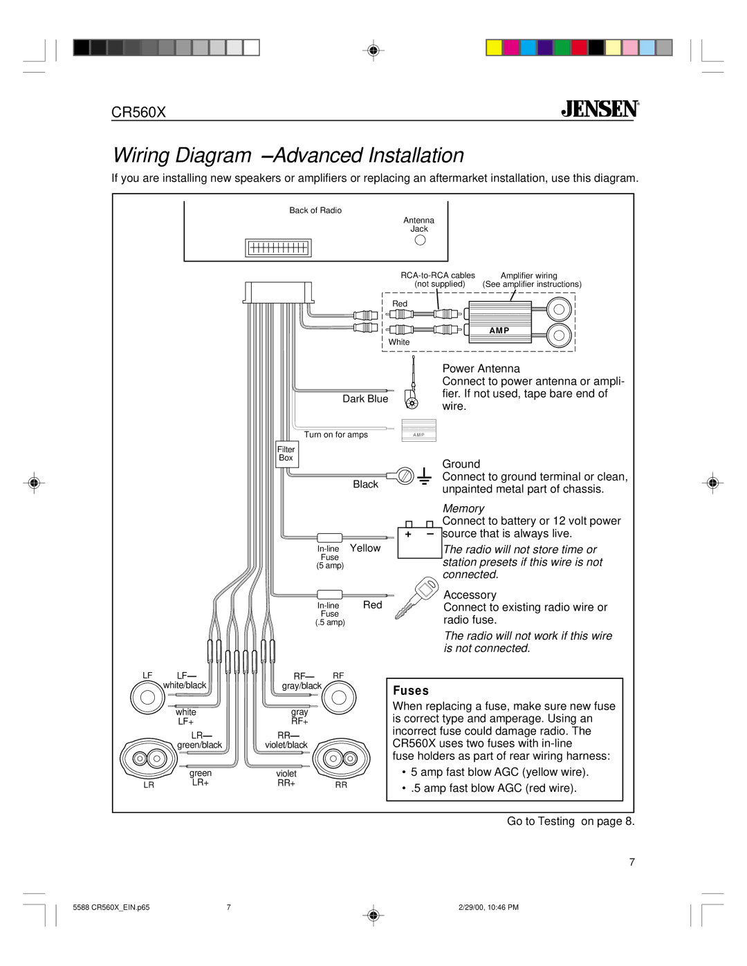
In terms of installation, the Jensen CR560X is sized to fit standard car stereo slots, making it a convenient upgrade for many vehicles. Its built-in features make it an ideal choice for those looking to enhance their car’s audio system without investing in extensive modifications.
Overall, the Jensen CR560X combines modern technology with practical usability, making it a reliable addition to any vehicle. With its Bluetooth connectivity, extensive audio playback options, and customizable audio settings, it caters to the needs of a diverse range of users looking for quality and convenience in their in-car entertainment.