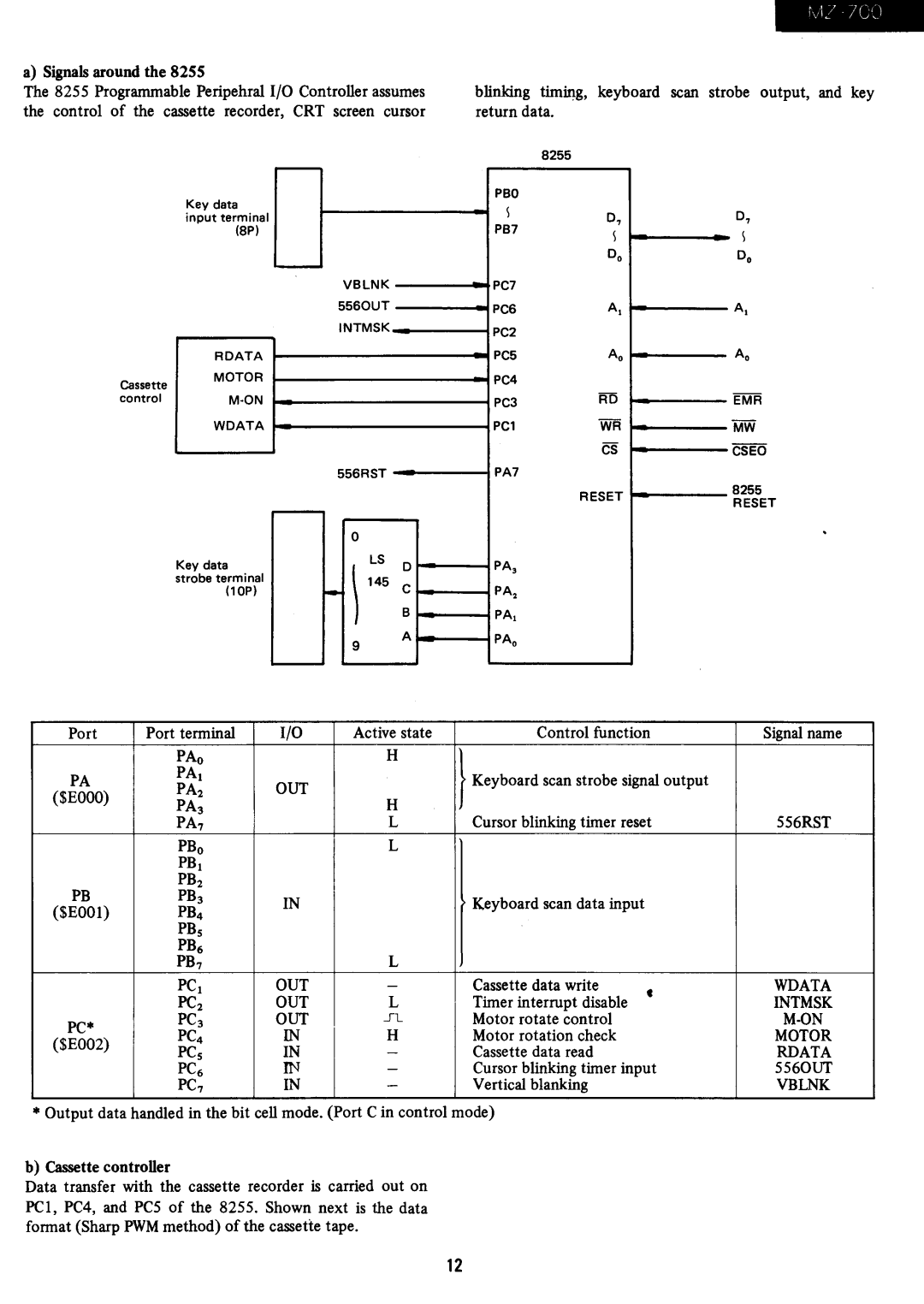
a) Signals around the 8255
The 8255 Programmable Peripehral I/O Controller assumes the control of the cassette recorder, CRT screen cursor
r
Key data input terminal
(8P)
' -
VBLNK 5560UT
INTMSK
| RDATA |
|
Cassette | MOTOR |
|
| ||
|
| |
control | M·ON |
|
| WDATA |
|
|
|
|
|
|
|
556RST
|
|
|
|
|
|
|
|
|
|
| 0 |
|
|
Key data |
| - |
| LS | 0 | |
| \ |
| ||||
strobe terminal |
| 145 | B | |||
(lOP) |
|
|
|
| C | |
|
|
|
| 9 |
| A |
|
|
|
|
|
| |
|
|
|
|
|
|
|
blinking timing, keyboard scan strobe output, and key return data.
8255
PBO
\ | 0, | 0, | ||
PB7 | ||||
\ |
|
| ||
|
|
| ||
| Do |
|
| |
PC7 |
|
|
| |
|
|
| ||
PC6 | AI |
| AI | |
| ||||
PC2 |
|
|
| |
PC5 | Ao |
|
| |
PC4 |
|
|
| |
PC3 | RD |
|
| |
PCl | WR |
|
| |
| CS |
|
| |
PA7 |
|
|
| |
| RESET | 8255 | ||
|
| RESET | ||
|
|
| ||
PA, |
|
|
| |
PA. |
|
|
| |
PAl |
|
|
| |
PAo |
|
|
| |
|
|
|
| |
Port | Port terminal | I/O | Active state | Control function | Signal name | |
| PAo |
| H |
|
|
|
PA | PAl | OUT |
| } Keyboud scan stwhe slgnal output |
| |
PA2 |
|
| ||||
($EOOO) | H |
|
|
| ||
| PA3 |
| Cursor blinking timer reset |
| ||
| PA7 |
| L | 556RST | ||
| PBo |
| L |
|
|
|
| PB I |
|
|
|
|
|
PB | PB2 |
|
|
|
|
|
PB 3 | IN |
| Keyboard scan data input |
|
| |
($EOOl) | PB4 |
|
|
| ||
|
|
|
|
| ||
| PBs |
|
|
|
|
|
| PB6 |
|
|
|
|
|
| PB 7 |
| L |
|
|
|
| PC I | OUT | - | Cassette data write | • | WDATA |
| PC2 | OUT | L | Timer interrupt disable | INTMSK | |
PC· | PC 3 | OUT | 51.. | Motor rotate control |
| |
PC4 | IN | H | Motor rotation check |
| MOTOR | |
($EOO2) |
| |||||
PCs | IN | - | Cassette data read |
| RDATA | |
|
| |||||
| PC6 | IN | - | Cursor blinking timer input | 5560UT | |
| PC 7 | IN | - | Vertical blanking |
| VBLNK |
• Output data handled in the bit cell mode. (Port C in control mode)
b) Cassette controller
Data transfer with the cassette recorder is carried out on PCI, PC4, and PC5 of the 8255. Shown next is the data format (Sharp PWM method) of the cassette tape.
12
