~1Z
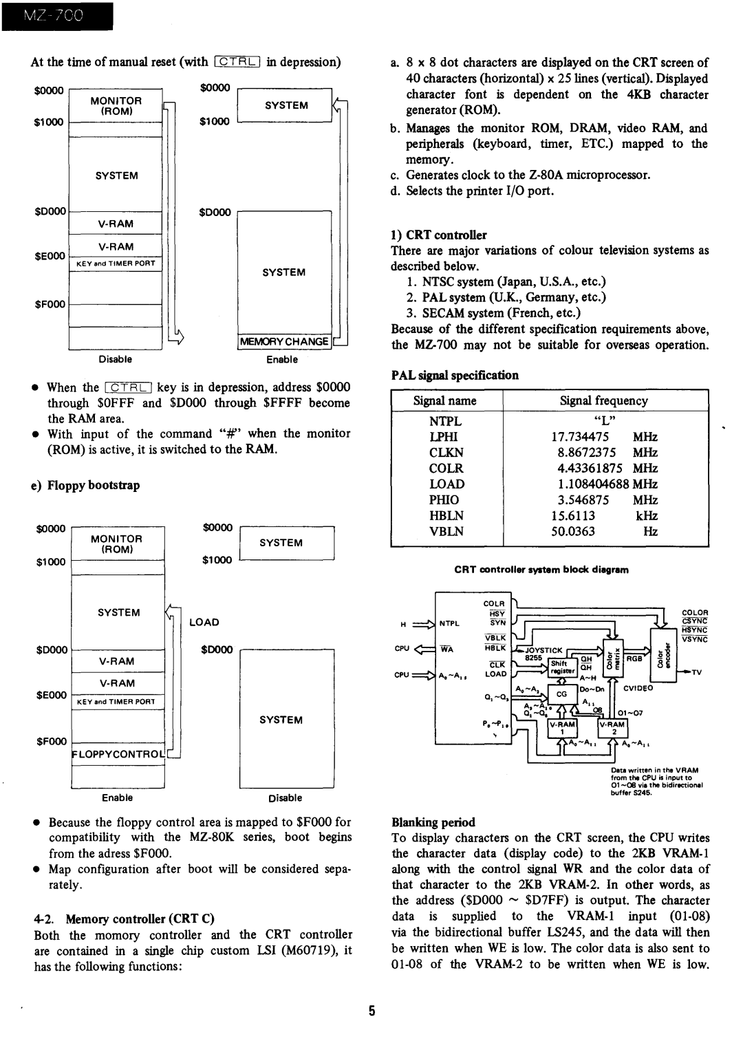
At the time of manual reset (with I CTRL I in depression)
a. 8 x 8 dot characters are displayed on the CRT screen of |
40 characters (horizontal) x 25 lines (vertical). Displayed |
$0000
$1000
$0000
$EOoo
$FOOO
MONITOR (ROM)
SYSTEM
KEY and TIMER PORT
Disable
$0000
-
$1000
$0000
~
SYSTEM ~
SYSTEM
MEMORY CHANGE '
Enable
character font is dependent on the 4KB character |
generator (ROM). |
b. Manages the monitor ROM, DRAM, video RAM, and peripherals (keyboard, timer, ETC.) mapped to the memory.
c.Generates clock to the
d.Selects the printer I/O port.
1) CRT controller
There are major variations of colour television systems as described below.
1.NTSC system (Japan, U.S.A., etc.)
2.PAL system (U.K., Germany, etc.)
3.SECAM system (French, etc.)
Because of the different specification requirements above, the
PAL signal specification
•When the I C T R L I key is in depression, address $0000 through $OFFF and $DOOO through $FFFF become the RAM area.
•With input of the command ":If' when the monitor (ROM) is active, it is switched to the RAM.
e) Floppy bootstrap
$0000 | .... |
|
|
|
|
|
|
| |
$0000 I | |||||||||
| MONITOR |
|
| ||||||
| (ROM) |
|
|
|
|
| SYSTEM | ||
|
|
| $1000 |
| |||||
$1000 | f |
|
|
| |||||
|
|
|
|
|
|
|
|
| |
| SYSTEM | iI- |
|
|
|
|
| ||
|
|
|
|
|
| ||||
| Iv |
| LOAD | ||||||
|
|
| |||||||
|
|
|
| ||||||
|
| $0000 |
|
| , |
| |||
|
|
|
| ||||||
|
|
|
|
|
|
|
| ||
|
|
|
|
|
|
|
|
| |
|
|
|
|
|
|
|
| ||
$EOoo |
|
|
|
|
|
|
| ||
| K Ey |
|
|
|
|
|
|
| |
|
|
|
|
|
|
| SYSTEM |
| |
$FOoo f |
|
|
|
|
|
|
| ||
| FLOPPYCONTRO~L |
| - |
|
|
|
|
| |
|
|
|
|
|
|
|
|
| |
EnableDisable
•Because the floppy control area is mapped to $FOOO for compatibility with the
•Map configuration after boot will be considered sepa- rately.
Both the momory controller and the CRT controller are contained in a single chip custom LSI (M60719), it has the following functions:
| Signal name |
|
| Signal frequency | ||
|
|
|
|
|
| |
| NTPL |
|
| "L" |
| |
| LPHI |
| 17.734475 | MHz | ||
| CLKN |
| 8.8672375 | MHz | ||
| COLR |
| 4.43361875 | MHz | ||
| WAD |
|
| 1.108404688 MHz | ||
| PHIO |
| 3.546875 | MHz | ||
| HBLN |
| 15.6113 | kHz | ||
| VBLN |
| 50.0363 | Hz | ||
|
|
|
|
| ||
|
| CRT controller system block diagram |
| |||
|
|
|
|
|
|
|
|
|
| COLR |
| ||
|
|
| HSY |
| ||
H |
| NTPL | SYN |
| ||
|
|
| VBLK |
| ||
CPU |
| WA | HBLK |
| ||
|
|
| CLK | TV | ||
CPU |
|
| LOAD | |||
Oata written in the VAAM
from the CPU is input to
buffer 5245.
Blanking period
To display characters on the CRT screen, the CPU writes the character data ( display code) to the 2KB
5