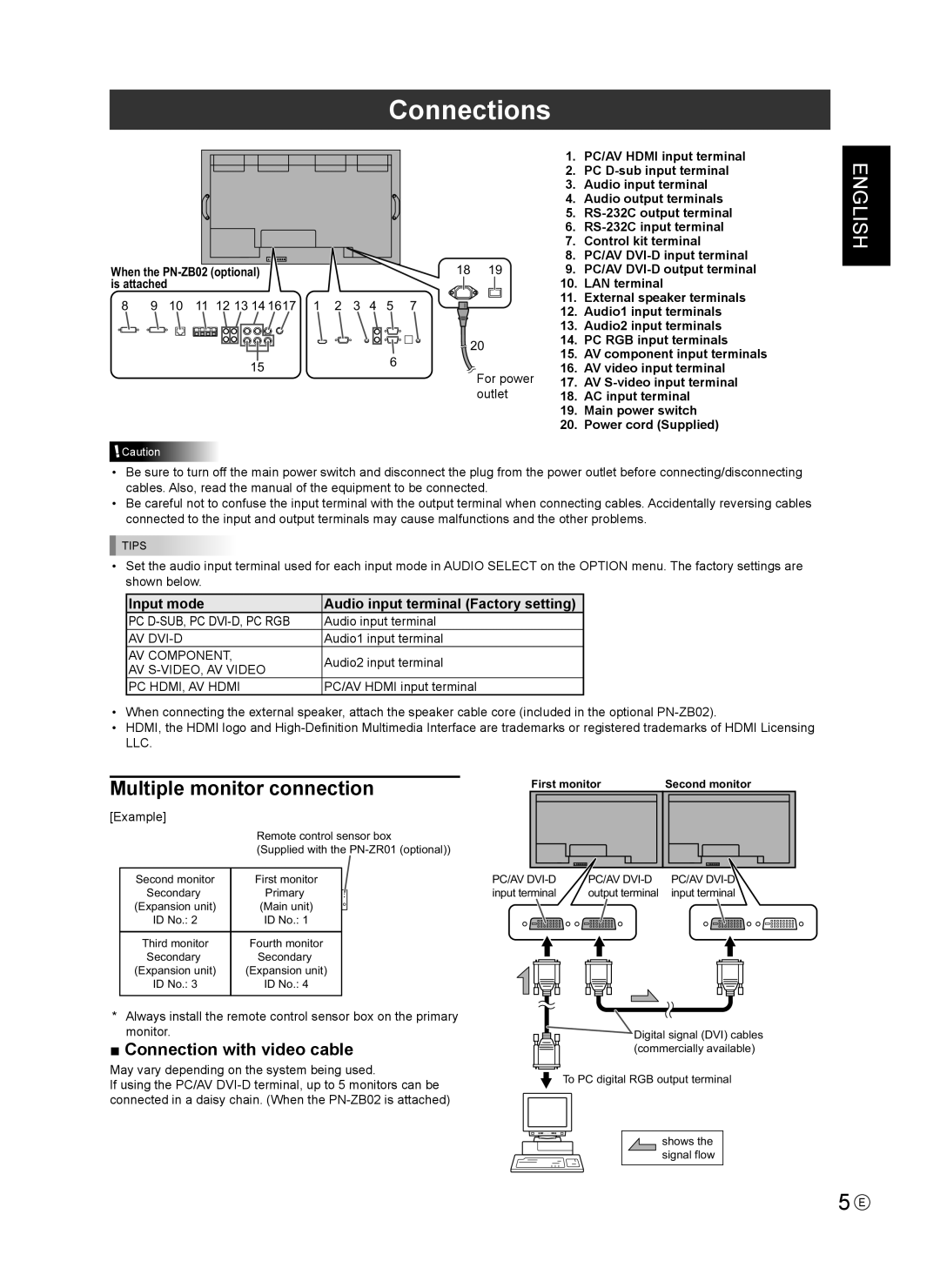
Connections
When the
8 | 9 | 10 | 11 | 12 13 14 1617 | 1 | 2 | 3 | 4 | 5 | |
|
|
|
|
|
|
|
|
|
|
|
|
|
|
|
|
|
|
|
|
|
|
156
![]() Caution
Caution
| 1. | PC/AV HDMI input terminal | |
| 2. | PC | |
| 3. | Audio input terminal | |
| 4. | Audio output terminals | |
| 5. | ||
| 6. | ||
| 7. | Control kit terminal | |
| 8. | PC/AV | |
18 19 | 9. | PC/AV | |
| 10. | LAN terminal | |
7 | 11. | External speaker terminals | |
12. | Audio1 input terminals | ||
| |||
| 13. | Audio2 input terminals | |
20 | 14. | PC RGB input terminals | |
15. | AV component input terminals | ||
| |||
For power | 16. | AV video input terminal | |
17. | AV | ||
outlet | 18. | AC input terminal | |
| 19. | Main power switch | |
| 20. | Power cord (Supplied) |
ENGLISH
•Be sure to turn off the main power switch and disconnect the plug from the power outlet before connecting/disconnecting cables. Also, read the manual of the equipment to be connected.
•Be careful not to confuse the input terminal with the output terminal when connecting cables. Accidentally reversing cables connected to the input and output terminals may cause malfunctions and the other problems.
![]() TIPS
TIPS
•Set the audio input terminal used for each input mode in AUDIO SELECT on the OPTION menu. The factory settings are shown below.
Input mode | Audio input terminal (Factory setting) | |
PC | Audio input terminal | |
AV | Audio1 input terminal | |
AV component, | Audio2 input terminal | |
AV | ||
| ||
PC HDMI, AV HDMI | PC/AV HDMI input terminal |
•When connecting the external speaker, attach the speaker cable core (included in the optional
•HDMI, the HDMI logo and
LLC.
Multiple monitor connection
[Example]
| Remote control sensor box | |
| (Supplied with the | |
|
|
|
Second monitor | First monitor |
|
Secondary | Primary |
|
(Expansion unit) | (Main unit) |
|
ID No.: 2 | ID No.: 1 |
|
|
|
|
Third monitor | Fourth monitor |
|
Secondary | Secondary |
|
(Expansion unit) | (Expansion unit) |
|
ID No.: 3 | ID No.: 4 |
|
|
|
|
*Always install the remote control sensor box on the primary monitor.
■ Connection with video cable
May vary depending on the system being used.
If using the PC/AV
First monitor | Second monitor | ||||||||
|
|
|
|
|
|
|
|
|
|
|
|
|
|
|
|
|
|
|
|
|
|
|
|
|
|
|
|
|
|
|
|
|
|
|
|
|
|
|
|
PC/AV | PC/AV | PC/AV |
input terminal | output terminal | input terminal |
![]() Digital signal (DVI) cables
Digital signal (DVI) cables
(commercially available)
![]() To PC digital RGB output terminal
To PC digital RGB output terminal
shows the signal flow
5 E
