Connections
■ Connection with RS-232 cable
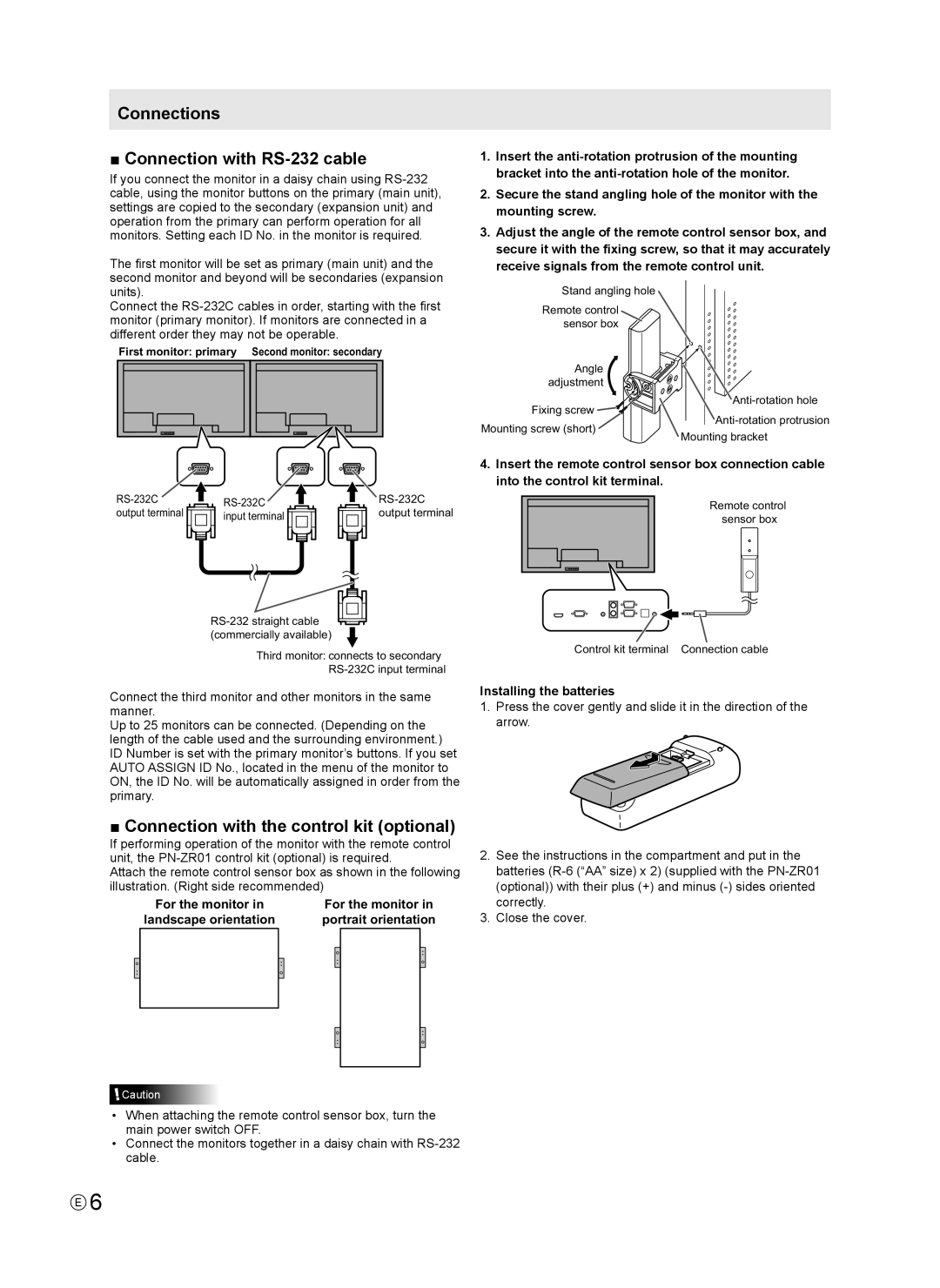
If you connect the monitor in a daisy chain using
The first monitor will be set as primary (main unit) and the second monitor and beyond will be secondaries (expansion units).
Connect the
First monitor: primary Second monitor: secondary
output terminal | input terminal | output terminal |
Third monitor: connects to secondary
Connect the third monitor and other monitors in the same manner.
Up to 25 monitors can be connected. (Depending on the length of the cable used and the surrounding environment.) ID Number is set with the primary monitor’s buttons. If you set AUTO ASSIGN ID No., located in the menu of the monitor to ON, the ID No. will be automatically assigned in order from the primary.
■ Connection with the control kit (optional)
If performing operation of the monitor with the remote control unit, the
Attach the remote control sensor box as shown in the following illustration. (Right side recommended)
For the monitor in | For the monitor in | ||
landscape orientation | portrait orientation | ||
|
|
|
|
|
|
|
|
![]() Caution
Caution
•When attaching the remote control sensor box, turn the main power switch OFF.
•Connect the monitors together in a daisy chain with
1.Insert the
2.Secure the stand angling hole of the monitor with the mounting screw.
3.Adjust the angle of the remote control sensor box, and secure it with the fixing screw, so that it may accurately receive signals from the remote control unit.
Stand angling hole
Remote control sensor box
Angle |
| |
adjustment |
| |
Fixing screw | ||
Mounting screw (short) | ||
Mounting bracket | ||
|
4.Insert the remote control sensor box connection cable into the control kit terminal.
Remote control sensor box
Control kit terminal Connection cable
Installing the batteries
1.Press the cover gently and slide it in the direction of the arrow.
2.See the instructions in the compartment and put in the batteries
3.Close the cover.
E6